



Share information:
Electrical diagrams for the car Peugeot 306

Electrical circuits — symbols on electrical circuits
The following symbols contain numbers found on various electrical diagrams, with leading letters, cable connections and ground points. Not all consumers are installed on all models. ВB00 Battery BB10 Battery BF00 Fuse...
The following symbols contain numbers found on various electrical diagrams, with leading letters, cable connections and ground points. Not all consumers are installed on all models. ВB00 Battery BB10 Battery BF00 Fuse...
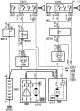
Electrical diagram of the starter and alternator (manual transmission)
Electrical diagram of the starter and alternator (manual transmission) Conventional symbols on electrical circuits here →
Electrical diagram of the starter and alternator (manual transmission) Conventional symbols on electrical circuits here →
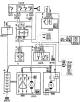
Electrical diagram of the starter and alternator (automatic transmission)
Electrical diagram of the starter and alternator (automatic transmission) Conventional symbols on electrical circuits here →
Electrical diagram of the starter and alternator (automatic transmission) Conventional symbols on electrical circuits here →

Electrical diagram of the starter, alternator and fuel heating system — engine xud9l
Electrical diagram of the starter, alternator and fuel heating system - engine XUD9L Conventional symbols on electrical circuits here →
Electrical diagram of the starter, alternator and fuel heating system - engine XUD9L Conventional symbols on electrical circuits here →

Electrical diagram of the starter, alternator, fuel heating system and speed meter — engine xud9l
Electrical diagram of the starter, alternator, fuel heating system and speed meter - engine XUD9L Conventional symbols on electrical circuits here →
Electrical diagram of the starter, alternator, fuel heating system and speed meter - engine XUD9L Conventional symbols on electrical circuits here →
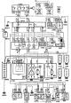
Electrical diagram of the starter, alternator, fuel heating system and speed meter — engine xud9tel
Electrical diagram of the starter, alternator, fuel heating system and speed meter - engine XUD9TEL Conventional symbols on electrical circuits here →
Electrical diagram of the starter, alternator, fuel heating system and speed meter - engine XUD9TEL Conventional symbols on electrical circuits here →
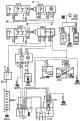
Electrical diagram of ignition, carburetor — engine tu3
Electrical diagram of ignition, carburetor - engine TU3 Conventional symbols on electrical circuits here →
Electrical diagram of ignition, carburetor - engine TU3 Conventional symbols on electrical circuits here →
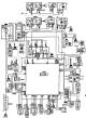
Ignition Wiring Diagram and Fuel Injection System (Magnetti, Morelli G6) — tu3 mcz/l engine
Electrical circuit diagram of the ignition system and fuel injection system (Magnetti, Morelli G6) - TU3 MCZ/L engine Conventional symbols on electrical circuits here →
Electrical circuit diagram of the ignition system and fuel injection system (Magnetti, Morelli G6) - TU3 MCZ/L engine Conventional symbols on electrical circuits here →
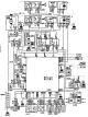
Electrical diagram of the ignition and fuel injection system (Bosch MA3.0) — engine tu3 mcz/l
Electrical diagram of the ignition and fuel injection system (Bosch MA3.0) - TU3 MCZ/L engine Conventional symbols on electrical circuits here →
Electrical diagram of the ignition and fuel injection system (Bosch MA3.0) - TU3 MCZ/L engine Conventional symbols on electrical circuits here →
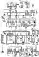
Electrical diagram of the ignition and fuel injection system (Bosch MP5.1) — engine tu5 jpz/l
Electrical diagram of the ignition and fuel injection system (Bosch MP5.1) - TU5 JPZ/L engine Conventional symbols on electrical circuits here →
Electrical diagram of the ignition and fuel injection system (Bosch MP5.1) - TU5 JPZ/L engine Conventional symbols on electrical circuits here →
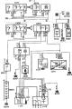
Electrical diagram of the ignition and fuel injection system (Magnetti Morelli 8P) — engine xu7 jpz/l
Electrical diagram of the ignition and fuel injection system (Magnetti Morelli 8P) - XU7 JPZ/L engine Conventional symbols on electrical circuits here →
Electrical diagram of the ignition and fuel injection system (Magnetti Morelli 8P) - XU7 JPZ/L engine Conventional symbols on electrical circuits here →
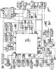
Electrical diagram of the ignition and fuel injection system (Magnetti Morelli 8P) — engine xu10 j2cz/l
Electrical diagram of the ignition and fuel injection system (Magnetti Morelli 8P) - engine XU10 J2CZ/L Conventional symbols on electrical circuits here →
Electrical diagram of the ignition and fuel injection system (Magnetti Morelli 8P) - engine XU10 J2CZ/L Conventional symbols on electrical circuits here →
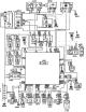
Electrical diagram of the ignition and fuel injection system (Magnetti Morelli 8P) — engine xu10 j2ck
Electrical diagram of the ignition and fuel injection system (Magnetti Morelli 8P) 0 engine XU10 J2CK Conventional symbols on electrical circuits here →
Electrical diagram of the ignition and fuel injection system (Magnetti Morelli 8P) 0 engine XU10 J2CK Conventional symbols on electrical circuits here →
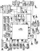
Electrical diagram of the ignition and fuel injection system (Magnetti Morelli 8P) — xu7 jpk engine
Electrical diagram of the ignition and fuel injection system (Magnetti Morelli 8P) - XU7 JPK engine Conventional symbols on electrical circuits here →
Electrical diagram of the ignition and fuel injection system (Magnetti Morelli 8P) - XU7 JPK engine Conventional symbols on electrical circuits here →

Electrical diagram of the ignition and fuel injection system (Magnetti Morelli 8P) — engine xu10 j4
Electrical diagram of the ignition and fuel injection system (Magnetti Morelli 8P) - XU10 J4 engine Conventional symbols on electrical circuits here →
Electrical diagram of the ignition and fuel injection system (Magnetti Morelli 8P) - XU10 J4 engine Conventional symbols on electrical circuits here →
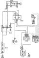
Electrical diagram of the cooling system, 1 fan, one rotation speed (controlled from the thermostat housing)
Electrical diagram of the cooling system, 1 fan, one rotation speed (adjustable from the thermostat housing) Conventional symbols on electrical circuits here →
Electrical diagram of the cooling system, 1 fan, one rotation speed (adjustable from the thermostat housing) Conventional symbols on electrical circuits here →
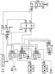
Electrical diagram of the cooling system, 2 fans, two rotation speeds (controlled by a thermostat switch)
Electrical diagram of the cooling system, 2 fans, two rotation speeds (regulated by a thermostat switch) Conventional symbols on electrical circuits here →
Electrical diagram of the cooling system, 2 fans, two rotation speeds (regulated by a thermostat switch) Conventional symbols on electrical circuits here →
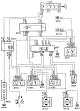
Electrical diagram of the cooling system, 2 fans, two rotation speeds (controlled from the thermostat housing)
Electrical diagram of the cooling system, 2 fans, two rotation speeds (adjustable from the thermostat housing) Conventional symbols on electrical circuits here →
Electrical diagram of the cooling system, 2 fans, two rotation speeds (adjustable from the thermostat housing) Conventional symbols on electrical circuits here →
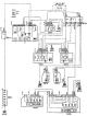
Rear fog lights / front fog lights wiring diagram
Rear fog lights / front fog lights wiring diagram Conventional symbols on electrical circuits here →
Rear fog lights / front fog lights wiring diagram Conventional symbols on electrical circuits here →

Electrical diagram of direction indicators, hazard warning lights
Electrical diagram of direction indicators, hazard warning lights Conventional symbols on electrical circuits here →
Electrical diagram of direction indicators, hazard warning lights Conventional symbols on electrical circuits here →
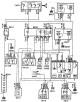
Electrical circuit of sound signals
Electrical circuit of sound signals Conventional symbols on electrical circuits here →
Electrical circuit of sound signals Conventional symbols on electrical circuits here →
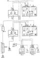
Low beam/high beam electrical circuit, without low beam relay
Low beam/high beam electrical circuit, without low beam relay Conventional symbols on electrical circuits here →
Low beam/high beam electrical circuit, without low beam relay Conventional symbols on electrical circuits here →
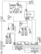
Parking light wiring diagram
Parking light wiring diagram Conventional symbols on electrical circuits here →
Parking light wiring diagram Conventional symbols on electrical circuits here →
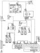
Interior lighting wiring diagram with time delay
Interior lighting wiring diagram with time delay Conventional symbols on electrical circuits here →
Interior lighting wiring diagram with time delay Conventional symbols on electrical circuits here →
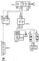
Interior lighting wiring diagram
Interior lighting wiring diagram Conventional symbols on electrical circuits here →
Interior lighting wiring diagram Conventional symbols on electrical circuits here →
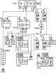
Interior lighting wiring diagram / ceiling lights (front and rear)
Interior lighting wiring diagram / ceiling lights (front and rear) Conventional symbols on electrical circuits here →
Interior lighting wiring diagram / ceiling lights (front and rear) Conventional symbols on electrical circuits here →
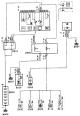
Electrical diagram of the instrument panel lighting, cigarette lighters and switches
Electrical diagram of the instrument panel lighting, cigarette lighters and switches Conventional symbols on electrical circuits here →
Electrical diagram of the instrument panel lighting, cigarette lighters and switches Conventional symbols on electrical circuits here →
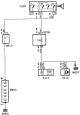
Glove box light wiring diagram
Glove box light wiring diagram Conventional symbols on electrical circuits here →
Glove box light wiring diagram Conventional symbols on electrical circuits here →

Electrical diagram of brake lights and reversing lights
Electrical diagram of brake lights and reversing lights Conventional symbols on electrical circuits here →
Electrical diagram of brake lights and reversing lights Conventional symbols on electrical circuits here →
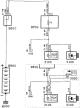
Wiring diagram for luggage compartment lighting
Wiring diagram for luggage compartment lighting Conventional symbols on electrical circuits here →
Wiring diagram for luggage compartment lighting Conventional symbols on electrical circuits here →
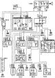
Headlight washer wiring diagram
Headlight washer wiring diagram Conventional symbols on electrical circuits here →
Headlight washer wiring diagram Conventional symbols on electrical circuits here →
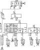
Electrical circuit for measuring engine oil level and pressure
Electrical circuit for measuring engine oil level and pressure Conventional symbols on electrical circuits here →
Electrical circuit for measuring engine oil level and pressure Conventional symbols on electrical circuits here →
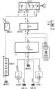
Electrical circuit diagram for measuring brake pad wear
Electrical circuit diagram for measuring brake pad wear Conventional symbols on electrical circuits here →
Electrical circuit diagram for measuring brake pad wear Conventional symbols on electrical circuits here →
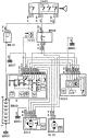
Wiring diagram of windshield wiper and washer
Wiring diagram of windshield wiper and washer Conventional symbols on electrical circuits here →
Wiring diagram of windshield wiper and washer Conventional symbols on electrical circuits here →
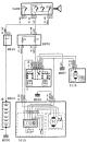
Rear windshield wiper and rear windshield washer wiring diagram
Rear windshield wiper and rear windshield washer wiring diagram Conventional symbols on electrical circuits here →
Rear windshield wiper and rear windshield washer wiring diagram Conventional symbols on electrical circuits here →

Electrical diagram of the electric window, front
Electrical diagram of the electric window, front Conventional symbols on electrical circuits here →
Electrical diagram of the electric window, front Conventional symbols on electrical circuits here →
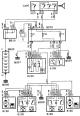
Electrical diagram of the electric window lift, rear
Electrical diagram of the electric window lift, rear Conventional symbols on electrical circuits here →
Electrical diagram of the electric window lift, rear Conventional symbols on electrical circuits here →
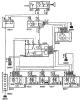
Electrical diagram of centrally controlled locks
Electrical diagram of centrally controlled locks Conventional symbols on electrical circuits here →
Electrical diagram of centrally controlled locks Conventional symbols on electrical circuits here →
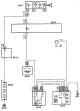
Electrical diagram of heating and ventilation
Electrical diagram of heating and ventilation Conventional symbols on electrical circuits here →
Electrical diagram of heating and ventilation Conventional symbols on electrical circuits here →
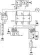
Rear window heating wiring diagram
Rear window heating wiring diagram Conventional symbols on electrical circuits here →
Rear window heating wiring diagram Conventional symbols on electrical circuits here →
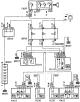
Electrical circuit for heated exterior mirrors
Electrical circuit for heated exterior mirrors Conventional symbols on electrical circuits here →
Electrical circuit for heated exterior mirrors Conventional symbols on electrical circuits here →
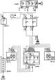
Electrical circuit for the exterior mirror drive
Electrical circuit for the exterior mirror drive Conventional symbols on electrical circuits here →
Electrical circuit for the exterior mirror drive Conventional symbols on electrical circuits here →
This section is available on russian, bulgarian, belarusian, ukrainian, serbian, croatian, romanian, polish, slovak, hungarian
See similar information for other Peugeot models
➨ Electrical equipment: Electrical diagrams Peugeot 106 (1991-2003)
➨ Electrical equipment: Electrical circuits Peugeot 206 (1998-2012)
➨ Electrical equipment: Electrical circuits Peugeot 406 (1995-2004)
➨ Electrical equipment: Electrical circuits Peugeot 605 (1989-2000)
➨ Electrical equipment: Electrical circuits Peugeot 807 (2002-2014)
Link to this section in different formats
TEXTHTMLBB Code
- User manual
- Keys, doors and alarm
- Controls and instruments
- Driving and operation
- Maintenance
- Power unit
- Petrol engines TU3 and TU5
- Petrol engines EW10
- Diesel engines DV10
- Diesel engines DW10
- Transmission
- Clutch and drive shafts
- Mechanical gearbox
- Automatic gearbox
- Chassis, running gear
- Front suspension
- Rear suspension
- Steering
- Brake system
- Body and interior
- Exterior (external elements)
- Interior (internal elements)
- Doors, locks and windows
- Heating and air conditioning
- Electrical equipment
- Equipment and devices
- Power devices
- Airbags
- Electrical circuits
- General information
- Introduction to manual
- Specifications
- Gasoline engine
- Engine repair
- Lubrication system
- Cooling system
- Fuel injection
- Ignition system
- Diesel engine
- Engine repair
- Lubrication system
- Cooling system
- Fuel injection
- Transmission
- Clutch
- Gearbox
- Drive shafts
- Chassis, running gear
- Steering system
- Front suspension
- Rear suspension
- Brake system
- Electrical equipment
- Power devices
- Electrical circuits
- General information
- Maintenance
- Power unit
- Gasoline engines
- Diesel engines
- Cooling system (gasoline)
- Cooling system (diesel)
- Fuel system (gasoline)
- Fuel system (diesel)
- Ignition system
- Transmission
- Clutch
- Mechanical gearbox BB8
- Mechanical gearbox BE1
- Automatic gearbox ZF4
- Shafts, hubs and wheels
- Chassis, running gear
- Brake system
- Car suspension
- Steering
- Body and interior
- Exterior (external elements)
- Interior (internal elements)
- Electrical equipment
- Equipment and devices
- Headlights and lighting
- Power devices
- Electrical circuits
- Wiring diagrams (diesel)