
Fuse table
Engine compartment fuse box
| Fuse | Rated current | Protected electrical circuit |
| F1 | 20A | headlight washer |
| F2 | Not used | |
| F3 | Z0A | Engine cooling fan |
| F4 | Not used | |
| F5 | Not used | |
| F6 | Z0A | ABS |
| F7 | Not used | |
| F8 | - | Not used |
| F9 | 10A | Fuel pump |
| F10 | 5A | Oxygen sensor |
| F11 | - | Not used |
| F12 | 10A | Right high beam headlight |
| F13 | 10A | Left high beam headlight |
| F14 | 10A | Right low beam headlight |
| F15 | 10A | Left low beam headlight |
Fuses type «Maxi» should only be replaced by the main dealer.
Interior fuse box
| Fuse | Rated current | Protected electrical circuit |
| F1 | 10A | Radio |
| F2 | 5A | The engine control unit. dashboard |
| F3 | 15A | ABS |
| F4 | 5A | Left front position lamp, right rear position lamp |
| F5 | - | Not used |
| F6 | 10A | Air conditioner |
| F7 | 20A | Horn, diagnostic connector |
| F8 | - | Shunt |
| F9 | 5A | Right front marker lamp, left rear marker lamp, license plate lamps |
| F10 | 20A | Power windows |
| F11 | 20A | Passenger window power window |
| F12 | 20A | Reversing lights. engine cooling fan, brake lights |
| F13 | 5A | Power window driver's window |
| F14 | 10A | Central locking |
| F15 | 10A | Central locking |
| F16 | 5A | cigarette lighter |
| F17 | Not used | |
| F18 | 5A | Rear fog lamp |
| F19 | 5A | Interior lighting |
| F20 | 25A | heater fan |
| F21 | 5A | Heated rear window, air conditioning |
| F22 | 20A | Rear window wiper motor |
| F23 | - | Shunt |
| F24 | 20A | Windshield Wiper Motor |
| F25 | 5A | Interior lighting, clock. air conditioning, engine control unit |
| F26 | 15A | Direction indicators, central locking |
| F27 | Z0A | Rear window heating |
| F28 | 15A | Power windows, power mirrors |
| F29 | Z0A | Air conditioning, seat heating |
| F30 | 10A | Direction indicators, instrument panel, interior lighting, central locking |
Name of typical schemes
| Scheme 1 | Information on electrical diagrams | |
| Scheme 2 | Starting and charging, audio system, horn, cigarette lighter, heated rear window, reversing lights | |
| Scheme 3 | Fog lights and rear fog lights, parking lights, license plate lights, brake lights, headlights, tail lights, direction indicators and hazard warning lights | |
| Scheme 4 | ABS, airbags, power windows, headlight range adjustment | |
| Scheme 5 | Front and rear washers/wipers, central locking with double locking | |
| Scheme 6 | Heater fan, engine cooling, air conditioning | |
| Scheme 7 | Instrument panel, interior lighting and electric mirror adjustment |
Grounding points to ground
| E1 | «Weight» battery |
| E2 | Below on the right A-pillar above point E10 |
| E3 | Behind the battery |
| E4 | Left wing |
| E5 | Down on the left A-pillar |
| E6 | Left under rear light |
| E7 | Right under rear light |
| E8 | Inner side of the right front fender |
| E9 | Behind the central part of the front panel |
| E10 | Down on the right A-pillar |
| E11 | Below on the left A-pillar above point E5 |
| E12 | «Weight» engine, before engine |
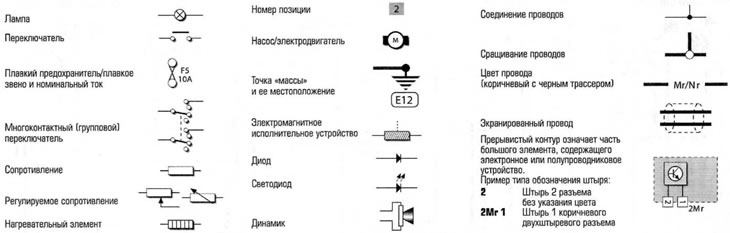
Conventions
Note
The main way to identify wires is to use pin numbers (pins) (indicated on each element or electrical connector and shown in the diagrams) together with the code number printed on each wire. To match each diagram to the car's wiring, locate the appropriate item or electrical connector shown in the diagram and locate the wire (-A), connected to the pin (-pits).
Warning. Although the number (denoting the function of this wire) should be indicated on each wire, this is not always the case, and in such cases this wire numbering is not shown in the diagrams here. Similarly, original information from manufacturers on the numbering of electrical connector pins is not always provided, and therefore it may not be available on our diagrams. In these cases, you may need to contact your dealer for more information.
Keep in mind that the usual way of using color coding does not apply: although the wires on the car are colored, the color of the wire does not have any specific meaning.