



Share information:
Vehicle wiring diagrams Peugeot 305
It's easy to check the Peugeot 305 electrical diagrams by model and year. Here you'll find wiring diagrams for the GL, GR, SR, GTX, Estate, and Van, as well as the key to the diagrams and central locking circuits. If the component isn't working, first locate its circuit and fuse. After repairs, check the connections against the diagram. This helps the mechanic read the diagrams without confusing them and diagnose the problem faster.

Key to the wiring diagrams (Fig. 10.15-10.18)
1 Headlight 2 Front direction indicator 3 Front side light 6 Generator 7 Oil pressure relay 8 Electromagnetic fan 9 Electromagnetic fan thermostat 10 Sound signal 12 Battery 13 Starter 15 Coolant temperature sensor 16...
1 Headlight 2 Front direction indicator 3 Front side light 6 Generator 7 Oil pressure relay 8 Electromagnetic fan 9 Electromagnetic fan thermostat 10 Sound signal 12 Battery 13 Starter 15 Coolant temperature sensor 16...
Key to the wiring diagrams of the latest models (Fig. 12.119-12.131)
B/Figure 12.119-12.131. Not all of the listed equipment is installed on every model. 1 Headlight 2 Front direction indicator 3 Front side light 4 Turn signal repeater 5 Starter relay 5A Neutral Gear Relay 6 Generator 7...
B/Figure 12.119-12.131. Not all of the listed equipment is installed on every model. 1 Headlight 2 Front direction indicator 3 Front side light 4 Turn signal repeater 5 Starter relay 5A Neutral Gear Relay 6 Generator 7...
Key to the wiring diagrams of the latest models (Fig. 12.132-12.138)
B/Figure 12.132-12.138. Not all of the listed equipment is installed on every model. 1 Cigarette lighter (front) 3 Cigarette lighter (rear) 5 Distributor 9 Idle speed control solenoid 10 Generator 11 Transistor (heater...
B/Figure 12.132-12.138. Not all of the listed equipment is installed on every model. 1 Cigarette lighter (front) 3 Cigarette lighter (rear) 5 Distributor 9 Idle speed control solenoid 10 Generator 11 Transistor (heater...
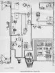
Fig. 10.15. Installation diagram — models gl and gr
Figure 10.15. Wiring diagram - GL and GR models The key to this wiring diagram is located here →
Figure 10.15. Wiring diagram - GL and GR models The key to this wiring diagram is located here →
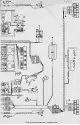
Fig. 10.16. Installation diagram — gl and gr models
Figure 10.16. Wiring diagram - GL and GR models The key to this wiring diagram is located here →
Figure 10.16. Wiring diagram - GL and GR models The key to this wiring diagram is located here →
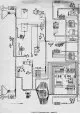
Fig. 10.17. Wiring diagram — sr models
Figure 10.17. Wiring diagram - SR models The key to this wiring diagram is located here →
Figure 10.17. Wiring diagram - SR models The key to this wiring diagram is located here →
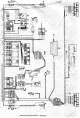
Fig. 10.18. Wiring diagram — sr models
Figure 10.18. Wiring diagram - SR models The key to this wiring diagram is located here →
Figure 10.18. Wiring diagram - SR models The key to this wiring diagram is located here →

Fig. 12.119. Installation diagram of the central locking system (typical)
Figure 12.119. Installation diagram of the central locking system (typical) The key to this wiring diagram is located here →
Figure 12.119. Installation diagram of the central locking system (typical) The key to this wiring diagram is located here →

Fig. 12.120. Installation diagram of the central locking system with keyless door locking and unlocking
Figure 12.120. Wiring diagram of the central locking system with keyless door locking and unlocking 82 Door lock switch 82A IR Transmitter 82V IR Receiver 83 Control unit 83A Auxiliary actuators 83C Main actuator The...
Figure 12.120. Wiring diagram of the central locking system with keyless door locking and unlocking 82 Door lock switch 82A IR Transmitter 82V IR Receiver 83 Control unit 83A Auxiliary actuators 83C Main actuator The...
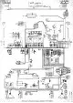
Fig. 12.121. Wiring diagram for GL models 1979 and 1980
Figure 12.121. Wiring diagram for GL models 1979 and 1980 The key to this wiring diagram is located here →
Figure 12.121. Wiring diagram for GL models 1979 and 1980 The key to this wiring diagram is located here →
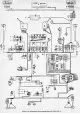
Fig. 12.122. Wiring diagram for Saloon and GL models 1980 and 1981
Figure 12.122. Wiring diagram for 1980 and 1981 Saloon and GL models The key to this wiring diagram is located here →
Figure 12.122. Wiring diagram for 1980 and 1981 Saloon and GL models The key to this wiring diagram is located here →
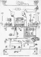
Fig. 12.123. Wiring diagram for Saloon and GL models produced since 1981
Figure 12.123. Wiring diagram for Saloon and GL models produced since 1981 1 Option on base 305 model 2 Except for the base 305 model The key to this wiring diagram is located here →
Figure 12.123. Wiring diagram for Saloon and GL models produced since 1981 1 Option on base 305 model 2 Except for the base 305 model The key to this wiring diagram is located here →
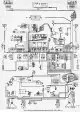
Fig. 12.124. Wiring diagram for GR and SR models 1979 and 1980
Figure 12.124. Wiring diagram for GR and SR models 1979 and 1980 1 Except GR models 2 Option The key to this wiring diagram is located here →
Figure 12.124. Wiring diagram for GR and SR models 1979 and 1980 1 Except GR models 2 Option The key to this wiring diagram is located here →
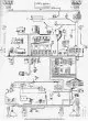
Fig. 12.125. Wiring diagram for GR and SR models 1980-1982
Figure 12.125. Wiring diagram for GR and SR models 1980-1982 1 Option. 2 Except GR models The key to this wiring diagram is located here →
Figure 12.125. Wiring diagram for GR and SR models 1980-1982 1 Option. 2 Except GR models The key to this wiring diagram is located here →
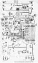
Fig. 12.126. Wiring diagram for SR models produced since 1983
Figure 12.126. Wiring diagram for SR models produced since 1983 The key to this wiring diagram is located here →
Figure 12.126. Wiring diagram for SR models produced since 1983 The key to this wiring diagram is located here →
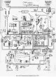
Fig. 12.127. Wiring diagram for S models produced since 1981
Figure 12.127. Wiring diagram for S models produced since 1981 1 Headlight cleaner parts The key to this wiring diagram is located here →
Figure 12.127. Wiring diagram for S models produced since 1981 1 Headlight cleaner parts The key to this wiring diagram is located here →
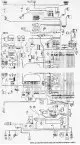
Fig. 12.128. Wiring diagram for GT models produced since 1983
Figure 12.128. Wiring diagram for GT models produced since 1983 The key to this wiring diagram is located here →
Figure 12.128. Wiring diagram for GT models produced since 1983 The key to this wiring diagram is located here →
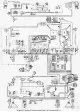
Fig. 12.129. Wiring diagram for Estate and Van models produced before 1981
Figure 12.129. Wiring diagram for Estate and Van models produced before 1981 1 Option The key to this wiring diagram is located here →
Figure 12.129. Wiring diagram for Estate and Van models produced before 1981 1 Option The key to this wiring diagram is located here →
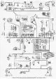
Fig. 12.130. Wiring diagram for Estate (except SR) and Van models produced since 1981
Figure 12.130. Wiring diagram for Estate (except SR) and Van models produced since 1981 1 Rear window wiper motor The key to this wiring diagram is located here →
Figure 12.130. Wiring diagram for Estate (except SR) and Van models produced since 1981 1 Rear window wiper motor The key to this wiring diagram is located here →
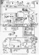
Fig. 12.131. Wiring diagram for GL and GR models 1986
Figure 12.131. Wiring diagram for GL and GR models 1986 1 Option The key to this wiring diagram is located here →
Figure 12.131. Wiring diagram for GL and GR models 1986 1 Option The key to this wiring diagram is located here →
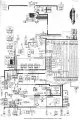
Fig. 12.132. Wiring diagram for 1986 Estate and Van models
Figure 12.132. Wiring diagram for 1986 Estate and Van models The key to this wiring diagram is located here →
Figure 12.132. Wiring diagram for 1986 Estate and Van models The key to this wiring diagram is located here →
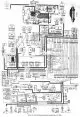
Fig. 12.133. Wiring diagram for GL and GR models 1986
Figure 12.133. Wiring diagram for GL and GR models 1986 The key to this wiring diagram is located here →
Figure 12.133. Wiring diagram for GL and GR models 1986 The key to this wiring diagram is located here →
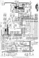
Fig. 12.134. Wiring diagram for GL and GR models 1987
Figure 12.134. Wiring diagram for GL and GR models 1987 The key to this wiring diagram is located here →
Figure 12.134. Wiring diagram for GL and GR models 1987 The key to this wiring diagram is located here →
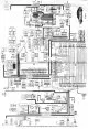
Fig. 12.135. Wiring diagram for Estate and GTX models with automatic transmission 1986
Figure 12.135. Wiring diagram for Estate and GTX models with automatic transmission 1986 The key to this wiring diagram is located here →
Figure 12.135. Wiring diagram for Estate and GTX models with automatic transmission 1986 The key to this wiring diagram is located here →
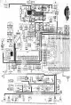
Fig. 12.136. Wiring diagram for Estate and GTX models with automatic transmission 1987
Figure 12.136. Wiring diagram for Estate and GTX models with automatic transmission 1987 The key to this wiring diagram is located here →
Figure 12.136. Wiring diagram for Estate and GTX models with automatic transmission 1987 The key to this wiring diagram is located here →
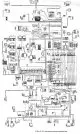
Fig. 12.137. Wiring diagram for GTX models
Figure 12.137. Wiring diagram for GTX models The key to this wiring diagram is located here →
Figure 12.137. Wiring diagram for GTX models The key to this wiring diagram is located here →
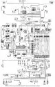
Fig. 12.138. Wiring diagram for GT models with automatic transmission
Figure 12.138. Wiring diagram for GT models with automatic transmission The key to this wiring diagram is located here →
Figure 12.138. Wiring diagram for GT models with automatic transmission The key to this wiring diagram is located here →

Fig. 12.139. Wiring diagram for the low beam headlight system
Figure 12.139. Wiring diagram for the low beam headlight system (models produced since 1987) A Power wire to the parking lights/headlights (dim lights) Power supply for normal low beam headlights With power supply for...
Figure 12.139. Wiring diagram for the low beam headlight system (models produced since 1987) A Power wire to the parking lights/headlights (dim lights) Power supply for normal low beam headlights With power supply for...
This section is available on russian, bulgarian, belarusian, ukrainian, serbian, croatian, romanian, polish, slovak, hungarian
See similar information for other Peugeot models
➨ Electrical equipment: Electrical diagrams Peugeot 106 (1991-2003)
➨ Electrical equipment: Electrical circuits Peugeot 206 (1998-2012)
➨ Electrical equipment: Electrical circuits Peugeot 406 (1995-2004)
➨ Electrical equipment: Electrical circuits Peugeot 605 (1989-2000)
➨ Electrical equipment: Electrical circuits Peugeot 807 (2002-2014)
Link to this section in different formats
TEXTHTMLBB Code
- User manual
- Keys, doors and alarm
- Controls and instruments
- Driving and operation
- Maintenance
- Power unit
- Petrol engines TU3 and TU5
- Petrol engines EW10
- Diesel engines DV10
- Diesel engines DW10
- Transmission
- Clutch and drive shafts
- Mechanical gearbox
- Automatic gearbox
- Chassis, running gear
- Front suspension
- Rear suspension
- Steering
- Brake system
- Body and interior
- Exterior (external elements)
- Interior (internal elements)
- Doors, locks and windows
- Heating and air conditioning
- Electrical equipment
- Equipment and devices
- Power devices
- Airbags
- Electrical circuits
- General information
- Introduction to manual
- Specifications
- Gasoline engine
- Engine repair
- Lubrication system
- Cooling system
- Fuel injection
- Ignition system
- Diesel engine
- Engine repair
- Lubrication system
- Cooling system
- Fuel injection
- Transmission
- Clutch
- Gearbox
- Drive shafts
- Chassis, running gear
- Steering system
- Front suspension
- Rear suspension
- Brake system
- Electrical equipment
- Power devices
- Electrical circuits
- General information
- Maintenance
- Power unit
- Gasoline engines
- Diesel engines
- Cooling system (gasoline)
- Cooling system (diesel)
- Fuel system (gasoline)
- Fuel system (diesel)
- Ignition system
- Transmission
- Clutch
- Mechanical gearbox BB8
- Mechanical gearbox BE1
- Automatic gearbox ZF4
- Shafts, hubs and wheels
- Chassis, running gear
- Brake system
- Car suspension
- Steering
- Body and interior
- Exterior (external elements)
- Interior (internal elements)
- Electrical equipment
- Equipment and devices
- Headlights and lighting
- Power devices
- Electrical circuits
- Wiring diagrams (diesel)