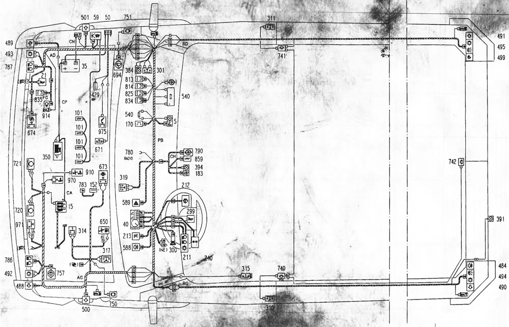
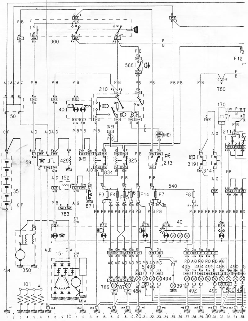
Conventional symbols on the electrical diagram of cars with diesel engines with a working volume of 2.5 liters produced since 1991
| 5 | Front cigarette lighter |
| 15 | Alternator |
| 21 | Right horn |
| 35 | Battery |
| 40 | Instrument cluster |
| 50 | Junction box |
| 101 | Glow plugs |
| 152 | Engine speed sensor |
| 170 | Flash frequency sensor |
| 183 | Heater fan switch |
| 210 | Light switch |
| 211 | Left switch |
| 212 | Right switch (wiper) |
| 213 | Parking light switch |
| 299 | Horn switch |
| 300 | Ignition switch |
| 301 | Glove compartment light switch |
| 310 | Left door contact switch |
| 311 | Right door contact switch |
| 314 | Reversing light switch |
| 315 | Handbrake lever switch |
| 317 | Low brake fluid level warning switch |
| 319 | Brake light switch |
| 350 | Starter |
| 384 | Glove compartment light |
| 391 | Left license plate light |
| 394 | Heater control panel backlight |
| 429 | Fuel shut-off solenoid valve |
| 484 | Rear fog light |
| 488 | Front left turn signal |
| 489 | Front right turn signal |
| 490 | Rear left turn signal |
| 491 | Rear right turn signal |
| 492 | Front right parking light |
| 493 | Front left parking light |
| 494 | Rear right parking/side light |
| 495 | Rear left parking/side light |
| 499 | Reversing light |
| 500 | Left side direction indicator |
| 501 | Right side turn signal |
| 540 | Fuses |
| 588 | Rear fog light switch |
| 589 | Flashing beacon switch |
| 650 | Fuel sensor |
| 671 | Oil pressure switch |
| 673 | Switch on the air filter |
| 674 | Turbocharger switch |
| 694 | Front windshield wiper |
| 720 | Left cooling system fan |
| 721 | Right cooling system fan |
| 740 | Interior light, left rear |
| 741 | Right rear interior light |
| 742 | Interior light, middle |
| 750 | Left brake pad wear indicator |
| 751 | Right brake pad wear indicator |
| 757 | Windshield washer pump |
| 765 | Radio |
| 780 | Supplying power to additional heating |
| 783 | Diagnostic connector |
| 786 | Left high/low beam headlight |
| 787 | Right high/low beam headlight |
| 790 | Heater fan motor |
| 813 | Left cooling fan relay |
| 814 | Right cooling fan relay |
| 825 | Low beam headlight relay |
| 834 | High beam headlight relay |
| 835 | Water condensate alarm relay in the filter |
| 859 | Heater fan motor ballast resistor |
| 910 | Coolant temperature sensor |
| 914 | Sensor for the presence of water condensate in the filter |
| 970 | Coolant temperature alarm switch |
| 971 | Temperature switch on the radiator |
| 975 | Oil temperature switch |
Material copied from the resource [peugeotbook.ru]
| A = | blue |
| BL = | blue |
| J = | yellow |
| N = | black |
| R = | red |
| V = | green |
| B = | white |
| G= | grey |
| M= | brown |
| O= | orange |
| Ro = | pink |
| Vi = | violet |
The cable harness layout diagram shows the location of the wire harnesses and the approximate location of consumers.
The circuit diagram shows various current circuits depending on their functions. These diagrams should be used when troubleshooting electrical equipment.