
Removing
1. Remove ground wire from battery.
Bosch Jetronic system
2. Remove the air flow meter.
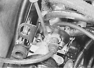
3. Remove the accelerator cable from the throttle actuator.
4. Drain coolant or pinch coolant hoses near housing.
5. Remove the multi-pin connector.
6. Loosen the clamps and remove the plastic pipe.
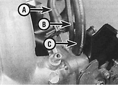
7. Remove coolant hose (A), vacuum hose (IN) and crankcase ventilation hose (WITH).
8. Unscrew the mounting bolts and remove the throttle body.
Bosch LU2-Jetronic system
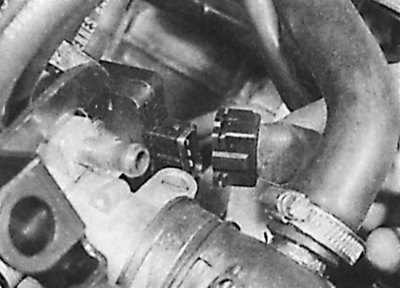
9. Disconnect the connector from the throttle position sensor.
10. Loosen the clamp and remove the air line from the front of the throttle body.
11. Remove the accelerator cable.
12. Remove the vacuum hose and crankcase breather hose.
13. Unscrew the three bolts and remove the throttle body.
Bosch Motronic system
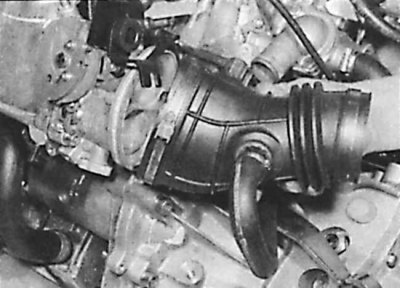
14. Loosen the clamp and remove the air supply pipe.
15. Remove the accelerator cable from the throttle control cam.
16. Disconnect the connectors from the throttle position sensor, heater element and air temperature sensor.
17. Unscrew the three bolts and remove the throttle body from the intake manifold along with the O-ring to be replaced.
Magneti Marelli 8P system
18. Remove air filter.
19. Remove the accelerator cable from the throttle control cam.
20. Disconnect the connectors from the throttle position sensor, heater element, air temperature sensor, and idle control motor.
21. Remove the vacuum hose and crankcase breather hose.
22. Unscrew the three bolts and remove the throttle body from the intake manifold along with the O-ring to be replaced.
Installation
Installation is carried out in the reverse order of removal, it is necessary to take into account:
- always use only a new o-ring, which is installed on the manifold, and then carefully install the throttle body;
- check the correct installation of previously removed hoses;
- check the correct installation of previously removed connectors;
- install the accelerator cable.
Electronic control device
With the exception of the Bosch L3.1-Jetronic system, the electronic control unit is located behind the bulkhead of the engine compartment on the left side.
1. Remove ground wire from battery.
2. Remove the protective cover from the bulkhead of the engine compartment.
3. Disconnect the bracket and remove the connector from the electronic control device.
4. Unscrew the bolts securing the ECU housing and remove it. On some models, it may be necessary to disconnect the ground wire.
5. Installation is carried out in the reverse order of removal.