



Share information:
Fuel system with carburetor Peugeot 405
Fuel pump — removal, inspection and installation
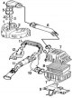
Fuel system with carburetor 1 – Intake manifold, 2 – Intake manifold gasket, 3 – Carburetor, 4 – Carburetor inlet pipe, 5 – Joint, 6 – Air duct, 7 – Air filter housing, 8 – Replaceable air filter element, 9 – Bracket,...
Fuel system with carburetor 1 – Intake manifold, 2 – Intake manifold gasket, 3 – Carburetor, 4 – Carburetor inlet pipe, 5 – Joint, 6 – Air duct, 7 – Air filter housing, 8 – Replaceable air filter element, 9 – Bracket,...

Fuel level sensor in the tank
Removal and installation 1. Remove the ground wire from the battery. 2. To access the sensor, remove the rear seats. 3. Remove the plastic cover to access the fuel level sensor in the tank. 4. Disconnect the wires and...
Removal and installation 1. Remove the ground wire from the battery. 2. To access the sensor, remove the rear seats. 3. Remove the plastic cover to access the fuel level sensor in the tank. 4. Disconnect the wires and...

Fuel tank — removal and installation
Fuel tank breather connector 8 – cover, 9 – central seal, 10 – hose Removal 1. Before removing the fuel tank, all fuel must be drained. 2. Remove the exhaust system and heat shields. 3. Remove the handbrake cable. 4....
Fuel tank breather connector 8 – cover, 9 – central seal, 10 – hose Removal 1. Before removing the fuel tank, all fuel must be drained. 2. Remove the exhaust system and heat shields. 3. Remove the handbrake cable. 4....

Removal and installation the carburetor
Installing the locking bracket on the accelerator cable 1. In the engine compartment, remove the accelerator cable from the throttle lever and the outer casing of the cable from the sealing ring (the fastening of the...
Installing the locking bracket on the accelerator cable 1. In the engine compartment, remove the accelerator cable from the throttle lever and the outer casing of the cable from the sealing ring (the fastening of the...

Disassembling the carburetor
Solex 34/34 Z1 carburetor section A – first chamber, B – second chamber 1 – idle fuel jet; 2 – air jet; 3 – float; 4 – needle valve; 5 – diffuser; 6 – main fuel jet; 7 – well of the transition system of the second...
Solex 34/34 Z1 carburetor section A – first chamber, B – second chamber 1 – idle fuel jet; 2 – air jet; 3 – float; 4 – needle valve; 5 – diffuser; 6 – main fuel jet; 7 – well of the transition system of the second...

Carburetor operation
Starting a cold engine The air damper is closed due to the operation of the element expanding under the influence of heat. During start-up, the engine vacuum causes intensive fuel suction with a reduced amount of air....
Starting a cold engine The air damper is closed due to the operation of the element expanding under the influence of heat. During start-up, the engine vacuum causes intensive fuel suction with a reduced amount of air....

Carburetor adjustment
Adjusting the fuel level in the float chamber Checking the float adjustment (fuel level in the float chamber) and a template drawing 1 – adjusting tongue 1. Remove the carburetor cover. 2. Turn over the lid with the...
Adjusting the fuel level in the float chamber Checking the float adjustment (fuel level in the float chamber) and a template drawing 1 – adjusting tongue 1. Remove the carburetor cover. 2. Turn over the lid with the...

OVAD Launcher
Installing an auxiliary valve for opening the starting diaphragm 2 – connector, 3 – second membrane, 4 – tank Auxiliary valve for opening the starting diaphragm (scheme of work) 1 – adjusting screw, 2 – calibrated jet,...
Installing an auxiliary valve for opening the starting diaphragm 2 – connector, 3 – second membrane, 4 – tank Auxiliary valve for opening the starting diaphragm (scheme of work) 1 – adjusting screw, 2 – calibrated jet,...
Engine post-cooling
The special device has a temperature sensor, two reversing relays and a clock element in the carburetor stand. Characteristic Temperature sensor: – switch-on temperature 57°C – switch-off temperature 52°C Time delay 12...
The special device has a temperature sensor, two reversing relays and a clock element in the carburetor stand. Characteristic Temperature sensor: – switch-on temperature 57°C – switch-off temperature 52°C Time delay 12...

Intake manifold — removal and installation
Removal 1. Remove the carburetor. 2. Disconnect the brake booster hose from the manifold. 3. Disconnect the ventilation system hose from the manifold. 4. Unscrew the bolt from the oil can pipe hanger. 5. Unscrew the...
Removal 1. Remove the carburetor. 2. Disconnect the brake booster hose from the manifold. 3. Disconnect the ventilation system hose from the manifold. 4. Unscrew the bolt from the oil can pipe hanger. 5. Unscrew the...

Exhaust manifold — removal and installation
Location of gaskets on the exhaust ports on the cylinder head Removal 1. Disconnect the hot air supply hose to the engine fuel system from the exhaust manifold. 2. Remove the screws and remove the cover from the top of...
Location of gaskets on the exhaust ports on the cylinder head Removal 1. Disconnect the hot air supply hose to the engine fuel system from the exhaust manifold. 2. Remove the screws and remove the cover from the top of...
This section is available on russian, bulgarian, belarusian, ukrainian, serbian, croatian, romanian, polish, slovak, hungarian
See similar information for other Peugeot models
➨ Power unit: Fuel system (diesel) Peugeot 106 (1991-2003)
➨ Power unit: Fuel system (gasoline) Peugeot 207 (2006-2014)
➨ Power unit: Fuel system (gasoline) Peugeot 305 (1977-1989)
➨ Power unit: Fuel system Peugeot 605 (1989-2000)
➨ Power unit: Fuel system Peugeot 807 (2002-2014)
Link to this section in different formats
TEXTHTMLBB Code
- General information
- User manual
- Maintenance (gasoline)
- Maintenance (diesel)
- Power unit
- Gasoline engines
- Diesel engines
- Engine overhaul
- Cooling and heating
- Fuel system (gasoline)
- Fuel system (diesel)
- Engine electrical equipment
- Transmission
- Clutch and drive shafts
- Mechanical gearbox
- Automatic gearbox
- Chassis, running gear
- Brake system
- Car suspension
- Steering
- Body and interior
- Exterior (external elements)
- Interior (internal elements)
- Doors, locks and windows
- Electrical equipment
- Equipment and devices
- Electrical circuits
- General information
- User manual
- Maintenance
- Power unit
- Petrol engines 1.4 l
- Petrol engines 1.6-2.0 l
- Diesel engines
- Ignition system
- Fuel system (carburetor)
- Single point fuel injection
- Multipoint fuel injection
- Cooling and lubrication system
- Exhaust system
- Transmission
- Clutch
- Manual gearbox MA
- Manual gearbox BE
- Automatic gearbox
- Drive shafts
- Chassis, running gear
- Steering
- Front suspension
- Rear suspension
- Brake system
- Body and interior
- Exterior (external elements)
- Interior (internal elements)
- Doors, locks and windows
- Electrical equipment
- Equipment and devices
- Electrical circuits