
Section of the carburetor Solex 34/34 Z1
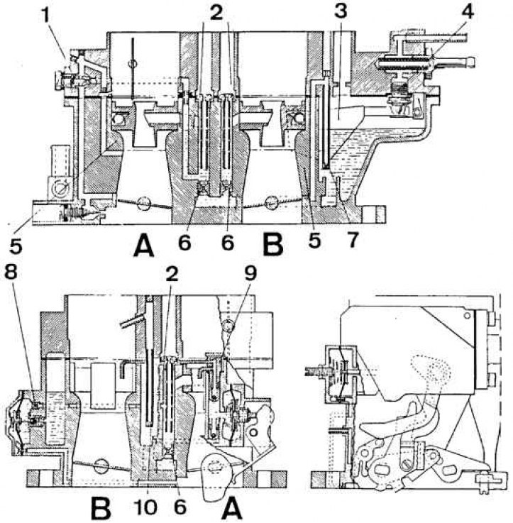
A - the first chamber, B - the second chamber
1 - idle fuel jet; 2 - air jet; 3 - float; 4 - needle valve; 5 - diffuser; 6 - main fuel jet; 7 - well of the transition system of the second chamber; 8 - accelerating pump; 9 - accelerator pump sprayer; 10 - enrichment device well
Solex carburetor
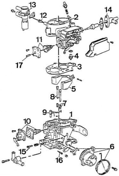
1 - carburetor body; 2 - cover; 3 - gasket; 4 - needle valve; 5 - float; 6 - throttle control system; 7 - fuel jet; 8 - air jet with emulsion tubes; 9 - accelerator pump sprayer; 10 - accelerating pump; 11 - starting device; 12 - idle fuel jet; 13 - float chamber deaerator; 14 - thermostatic device for controlling the air damper; 15 - screw for adjusting the amount of the mixture; 16 - screw for adjusting the composition of the mixture; 17 - adjustment screw for slightly opening the air damper
1. Remove the carburetor from the vehicle.
2. Unscrew the solenoid valve with plunger and spring from the carburetor and check its operation. To check, connect the negative terminal of the battery to the valve body, and the positive terminal to the valve terminal, the plunger must be fully retracted. After disconnecting the valve from the accumulator, the spring should push the plunger out of the valve.
3. Unscrew 5 screws and remove the carburetor cover.
4. Remove the float axle, remove the floats and gasket.
5. Unscrew the fuel inlet fitting, remove the fuel filter and check its condition. Clean the filter if necessary.
6. Unscrew the 4 screws and remove the accelerator pump cover, diaphragm and spring. Check diaphragm integrity.
7. Unscrew the idle jet from the cover.
8. Unscrew the emulsion tubes.
9. Using a long, thin screwdriver, unscrew the main jets from the emulsion wells.
10. Turn the carburetor over and shake out the jets.
11. Unscrew the idle adjustment screw, while counting the number of revolutions that you need to know when screwing the screw into place.
12. Blow out the carburetor channels and float chambers with compressed air.
13. Check the carburetor heating element by measuring its resistance, which should be 0.25–0.5 ohms.
14. The carburetor is assembled in the reverse order of disassembly, after which it is necessary to adjust the carburetor.