



Share information:
Petrol engines 1.6, 1.8, 1.9 and 2.0 l Peugeot 405

Petrol engines 1.6-2.0 l — design description
Gasoline engine (8 valves) in section The engine is a four-stroke, four-cylinder, in-line, transversely mounted at the front of the vehicle. Engines with a working volume of 1905 cc and 1998 cc with 16 valves have two...
Gasoline engine (8 valves) in section The engine is a four-stroke, four-cylinder, in-line, transversely mounted at the front of the vehicle. Engines with a working volume of 1905 cc and 1998 cc with 16 valves have two...

Technical characteristics of engines 1.6-2.0 liters
Engine Cylinder head The head is made of light alloy and has inserted valve seats and guides. The camshaft bearings are made of the cylinder head material. Nominal height: – engines 1580 cm³, 1761 cm³ and 1905 cm³ (with...
Engine Cylinder head The head is made of light alloy and has inserted valve seats and guides. The camshaft bearings are made of the cylinder head material. Nominal height: – engines 1580 cm³, 1761 cm³ and 1905 cm³ (with...

Repairs that do not require engine removal
The following operations can be performed on the engine installed in the vehicle: compression check; removing and installing the cylinder head; removing and installing the crankshaft pulley; removing and installing the...
The following operations can be performed on the engine installed in the vehicle: compression check; removing and installing the cylinder head; removing and installing the crankshaft pulley; removing and installing the...
Checking the compression in the cylinders
In case of a decrease in engine power, which is not a defect of the ignition or fuel system, a compression test can determine the condition of the engine. If the test is performed regularly, it is possible to determine...
In case of a decrease in engine power, which is not a defect of the ignition or fuel system, a compression test can determine the condition of the engine. If the test is performed regularly, it is possible to determine...

Checking and adjusting valve clearance
Valve clearance should only be adjusted if incorrect adjustment is detected, valves are replaced or ground in, or tappets or camshafts are replaced. Examination Models 1905 cc and 1998 cc with 16 valves The 1905cc and...
Valve clearance should only be adjusted if incorrect adjustment is detected, valves are replaced or ground in, or tappets or camshafts are replaced. Examination Models 1905 cc and 1998 cc with 16 valves The 1905cc and...

Camshaft drive belt
Gas distribution system 1 – crankshaft; 2 – timing drive pulley; 3 – toothed belt; 4 – coolant pump; 5 – tension roller; 6 – eccentric screw; 7 – tension roller spring; 8 – camshaft pulley; 9 – camshaft; 10 – mounting...
Gas distribution system 1 – crankshaft; 2 – timing drive pulley; 3 – toothed belt; 4 – coolant pump; 5 – tension roller; 6 – eccentric screw; 7 – tension roller spring; 8 – camshaft pulley; 9 – camshaft; 10 – mounting...

Timing Belt Pulleys
1. Remove the ground wire from the battery. 2. Loosen and remove the alternator drive belt. 3. Remove the camshaft drive belt covers. 4. Using the pulley bolt, turn the crankshaft so that the timing drive elements are...
1. Remove the ground wire from the battery. 2. Loosen and remove the alternator drive belt. 3. Remove the camshaft drive belt covers. 4. Using the pulley bolt, turn the crankshaft so that the timing drive elements are...
Replacing the camshaft seal
Attention! The presence of traces of engine oil on the head on the toothed belt side indicates that the camshaft seal is out of order and needs to be replaced. 1. Remove the pulley from the camshaft. 2. Drill two holes...
Attention! The presence of traces of engine oil on the head on the toothed belt side indicates that the camshaft seal is out of order and needs to be replaced. 1. Remove the pulley from the camshaft. 2. Drill two holes...

Replacing crankshaft seals
Right seal 1. Remove the pulley from the crankshaft. 2. Drill two holes in the seal on two diametrically opposite sides and screw self-tapping screws into them. Pull the seal out using pliers by the screw heads. 3....
Right seal 1. Remove the pulley from the crankshaft. 2. Drill two holes in the seal on two diametrically opposite sides and screw self-tapping screws into them. Pull the seal out using pliers by the screw heads. 3....
Generator drive belt
Installing a used belt 1. Remove the crankshaft pulley. 2. Install plastic covers: lower right, upper, lower left. 3. Install the flywheel locking device (Facom D 86) and tighten the crankshaft pulley mounting bolt to a...
Installing a used belt 1. Remove the crankshaft pulley. 2. Install plastic covers: lower right, upper, lower left. 3. Install the flywheel locking device (Facom D 86) and tighten the crankshaft pulley mounting bolt to a...

Air Filter — Carburetor Models
1. Unscrew the clamp and remove the air duct from the carburetor. 2. Unscrew the clamp (indicated by the arrow) and remove the air supply tube from the filter housing cover. 3. Disconnect the clamps and remove the...
1. Unscrew the clamp and remove the air duct from the carburetor. 2. Unscrew the clamp (indicated by the arrow) and remove the air supply tube from the filter housing cover. 3. Disconnect the clamps and remove the...

Cylinder Head Cover — Removal and Installation
Nuts located under the cylinder head cover of 1761 cc and 1998 cc models (with 8 valves) The nuts are indicated by arrows. Removal Engines 1580 cm³ and 1905 cm³ (8 valves) 1. Remove the ground wire from the battery. 2....
Nuts located under the cylinder head cover of 1761 cc and 1998 cc models (with 8 valves) The nuts are indicated by arrows. Removal Engines 1580 cm³ and 1905 cm³ (8 valves) 1. Remove the ground wire from the battery. 2....

Camshaft — Removal, Inspection and Installation
Sequence of fastening bolts of camshaft bearing caps (1998 cc models with 16 valves) Removal 1. Remove the ground wire from the battery. 2. Remove the cylinder head cover. 1905cc 16 valve models 3. Remove the bolt from...
Sequence of fastening bolts of camshaft bearing caps (1998 cc models with 16 valves) Removal 1. Remove the ground wire from the battery. 2. Remove the cylinder head cover. 1905cc 16 valve models 3. Remove the bolt from...

Removal and installation the cylinder head
Special mounting posts for the rear part of the toothed belt drive guard Cylinder head 1 - cylinder head, 2 - cylinder head gasket, 3 - valve guide, 4 - valve seat, 5 - camshaft bearing cover, 6 - oil line, 7 - camshaft...
Special mounting posts for the rear part of the toothed belt drive guard Cylinder head 1 - cylinder head, 2 - cylinder head gasket, 3 - valve guide, 4 - valve seat, 5 - camshaft bearing cover, 6 - oil line, 7 - camshaft...

Disassembly, repair and assembly of the cylinder head
Disassembly 1. Place the cylinder head in the front and rear parts on two wooden blocks. 2. Remove the intake manifold together with the carburetor, as well as the exhaust manifold. 3. Remove the distributor and fuel...
Disassembly 1. Place the cylinder head in the front and rear parts on two wooden blocks. 2. Remove the intake manifold together with the carburetor, as well as the exhaust manifold. 3. Remove the distributor and fuel...

Removal the engine with a manual transmission
Opening the hood 1 – normal position, 2 – vertical position Engine mount brackets 1 – metal-rubber support of the gearbox, 2 – metal-rubber element mounting axis, 3 – engine bracket, 4 – metal-rubber support bracket, 5...
Opening the hood 1 – normal position, 2 – vertical position Engine mount brackets 1 – metal-rubber support of the gearbox, 2 – metal-rubber element mounting axis, 3 – engine bracket, 4 – metal-rubber support bracket, 5...
Removal the engine with automatic transmission
The engine and automatic transmission can only be removed together. Removing the engine is done in a similar way removal with manual transmission transmission. Additionally required: remove the dipstick tube to measure...
The engine and automatic transmission can only be removed together. Removing the engine is done in a similar way removal with manual transmission transmission. Additionally required: remove the dipstick tube to measure...
Engine installation
Caution: It is recommended to systematically replace the differential seals and self-locking nuts that have been removed. 1. Install the engine in the engine compartment. 2. Install the elastic support of the gearbox...
Caution: It is recommended to systematically replace the differential seals and self-locking nuts that have been removed. 1. Install the engine in the engine compartment. 2. Install the elastic support of the gearbox...

Disassembling the engine
Connecting rod and connecting rod cap marked for identification Cylinder #3 is shown. If possible, install the engine on a stand; if not, install it in such a way that the engine cannot be damaged when loosening tightly...
Connecting rod and connecting rod cap marked for identification Cylinder #3 is shown. If possible, install the engine on a stand; if not, install it in such a way that the engine cannot be damaged when loosening tightly...

Cleaning and checking parts before assembly
Attention! Some early engines use old type bolts in the cylinder head, i.e. hexagonal head bolts. In case of assembly of the cylinder liner-piston unit of the new type (cutout on cylinder liners) in an early production...
Attention! Some early engines use old type bolts in the cylinder head, i.e. hexagonal head bolts. In case of assembly of the cylinder liner-piston unit of the new type (cutout on cylinder liners) in an early production...
Crankshaft — assembly and installation
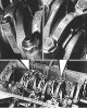
Designation of crankshaft main bearing caps and connecting rod bearing caps The crankshaft main bearing caps are numbered and have their projections facing the camshaft drive. The connecting rods and their caps are...
Designation of crankshaft main bearing caps and connecting rod bearing caps The crankshaft main bearing caps are numbered and have their projections facing the camshaft drive. The connecting rods and their caps are...
Connecting rod-piston unit — assembly and installation
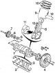
Crank mechanism 1 - crankshaft, 2 - main bearing shells, 3 - crankshaft thrust half rings, 4 - flywheel, 5 - oil pump drive sprocket, 6 - timing drive toothed pulley, 7 - V-pulley, 8 - connecting rod, 9 - piston, 10 -...
Crank mechanism 1 - crankshaft, 2 - main bearing shells, 3 - crankshaft thrust half rings, 4 - flywheel, 5 - oil pump drive sprocket, 6 - timing drive toothed pulley, 7 - V-pulley, 8 - connecting rod, 9 - piston, 10 -...
Connecting rod-pin-piston assembly — assembly and installation
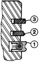
Typical piston ring placement order 1 – oil scraper ring, 2 – second sealing ring, 3 – upper sealing ring Installing the piston into the cylinder liner using a special piston ring holder Install the piston on the device...
Typical piston ring placement order 1 – oil scraper ring, 2 – second sealing ring, 3 – upper sealing ring Installing the piston into the cylinder liner using a special piston ring holder Install the piston on the device...
Starting the engine after major repairs
1. After installing the engine in the vehicle, check the oil and coolant levels. 2. Remove the spark plugs and turn off the ignition system. 3. Crank the engine with the starter until the oil pressure warning light goes...
1. After installing the engine in the vehicle, check the oil and coolant levels. 2. Remove the spark plugs and turn off the ignition system. 3. Crank the engine with the starter until the oil pressure warning light goes...
This section is available on russian, bulgarian, belarusian, ukrainian, serbian, croatian, romanian, polish, slovak, hungarian
See similar information for other Peugeot models
➨ Power unit: Petrol engines Peugeot 106 (1991-2003)
➨ Power unit: Gasoline engines Peugeot 206 (1998-2012)
➨ Power unit: Gasoline engines Peugeot 305 (1977-1989)
➨ Power unit: Petrol engines «XU» Peugeot 605 (1989-2000)
➨ Power unit: Petrol engines Peugeot Partner I (1996-2008)
Link to this section in different formats
TEXTHTMLBB Code
- General information
- User manual
- Maintenance (gasoline)
- Maintenance (diesel)
- Power unit
- Gasoline engines
- Diesel engines
- Engine overhaul
- Cooling and heating
- Fuel system (gasoline)
- Fuel system (diesel)
- Engine electrical equipment
- Transmission
- Clutch and drive shafts
- Mechanical gearbox
- Automatic gearbox
- Chassis, running gear
- Brake system
- Car suspension
- Steering
- Body and interior
- Exterior (external elements)
- Interior (internal elements)
- Doors, locks and windows
- Electrical equipment
- Equipment and devices
- Electrical circuits
- General information
- User manual
- Maintenance
- Power unit
- Petrol engines 1.4 l
- Petrol engines 1.6-2.0 l
- Diesel engines
- Ignition system
- Fuel system (carburetor)
- Single point fuel injection
- Multipoint fuel injection
- Cooling and lubrication system
- Exhaust system
- Transmission
- Clutch
- Manual gearbox MA
- Manual gearbox BE
- Automatic gearbox
- Drive shafts
- Chassis, running gear
- Steering
- Front suspension
- Rear suspension
- Brake system
- Body and interior
- Exterior (external elements)
- Interior (internal elements)
- Doors, locks and windows
- Electrical equipment
- Equipment and devices
- Electrical circuits