
Designation of crankshaft main bearing caps and connecting rod bearing caps
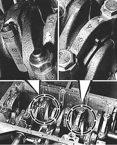
The crankshaft main bearing caps are numbered and lobed towards the camshaft drive. The connecting rods and their caps are marked with a special electric pencil.
Cylinder Block Assembly
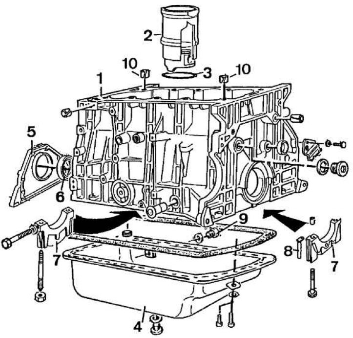
1 - cylinder block, 2 - cylinder liner, 3 - O-ring, 4 - oil pan, 5 - front main bearing cap, 6 - front O-ring, 7 - main bearing cap, 8 - rear main bearing cap gasket, 9 - drain coolant plug, 10 - bushings
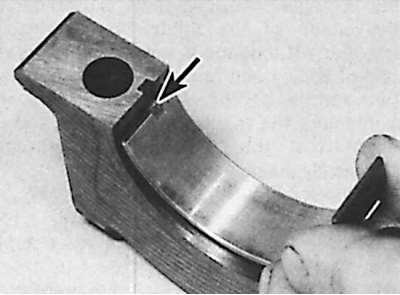
Installation of persistent half rings of a cranked shaft
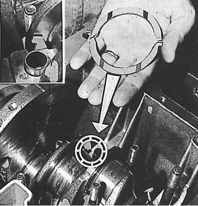
The lubrication grooves must be on the side of the crankshaft.
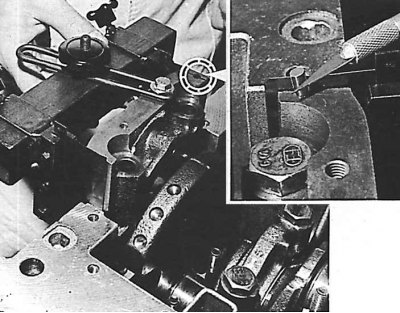
Installing #1 Main Bearing Cap with Gasket Installed
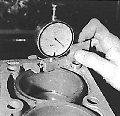
Checking the axial play of the crankshaft
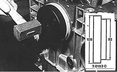
Installing the crankshaft sealing ring on the flywheel side - tool 7.0153 C
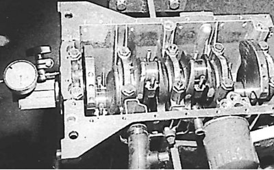
1. Install the crankshaft in the cylinder block (by first installing the liners lubricated with oil).
2. Install the crankshaft bearing caps lubricated with oil, following the markings (caps are numbered). The projections should be directed towards the camshaft drive (protrusion is indicated by an arrow).
Attention! When installing the bearing cover No. 2, insert 4 thrust half rings of the crankshaft with the sliding surface towards the crankshaft (see fig. Installation of persistent half rings of a cranked shaft).
3. Clean the connecting surfaces of the cylinder block and bearing cap No. 1, removing all traces of grease.
4. Apply a small amount of Loctite Frenetanch to the cylinder block at the top of the #1 bearing grooves.
5. Install the bearing cover on the adjusted tool 0153.A1. Bolt the cover to the fixture bracket (see fig. Installing #1 Main Bearing Cap with Gasket Installed).
6. Lubricate and secure the bearing cap in such a way that the side spacers do not lengthen:
- install the device-cover assembly inclined at 45°in its nest;
- straighten the knot;
- lower slowly;
- fix the cover with one bolt;
- remove the tool vertically.
7. Align the ends of the gasket relative to the surface of the cylinder block; after installation, they should protrude from the bearing to a height of 2±1 mm.
8. Check the crankshaft axial play and, if necessary, replace the crankshaft thrust half rings with half rings corresponding to this backlash (see fig. Checking the axial play of the crankshaft).
9. Using tool 0153.C, install the O-ring on the flywheel side (see fig. Installing the crankshaft sealing ring on the flywheel side - tool 7.0153 C).
10. Check protrusion of cylinder liners (this protrusion is the result of the ratio of the dimensions of the cylinder block and liner).
11. Insert four sleeves without gaskets.
12. Insert plate 8.0132 B (surface without edge should be directed upwards) and install the dial indicator on the bracket 8.0132 C.
13. Measure the protrusion of the liner in relation to the cylinder block at three points (0.08–0.15 mm).
14. Check the difference between the measured values for the measuring points and for the individual sleeves (maximum 0.05 mm).
Attention! If the sleeves are new, it is possible to change the protrusion of the sleeve and the difference in protrusion by turning 180°or changing the installation location in the cylinder block.
15. designate (from the side of the oil level indicator) cylinder liners from 1 to 4 (1 flywheel side).