
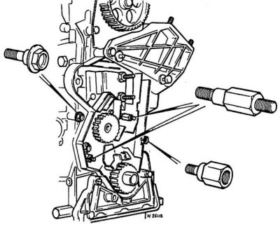
Special racks for fastening the rear part of the protection of the toothed belt drive
Cylinder head
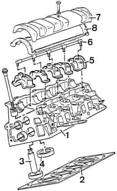
1 - cylinder head, 2 - cylinder head gasket, 3 - valve guide, 4 - valve seat, 5 - camshaft bearing cap, 6 - oil line, 7 - camshaft cover, 8 - gasket
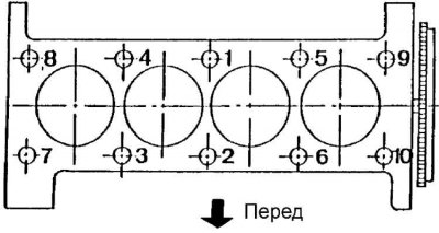
The order of tightening the cylinder head bolts
Removing
Engine models with 8 valves
1. Remove the camshaft drive belt.
2. Drain the liquid from the cooling system.
3. Loosen the bottom nut.
4. Remove the air filter assembly and air lines.
5. Remove the distributor cap and ignition wire harness.
6. Remove fuel pump.
7. Unscrew the nut of the elastic support of the right upper engine bracket.
8. Raise the engine to a height of 6-8 cm. If using a lift, the hood must be installed vertically.
9. Unscrew the bolts securing the right upper bracket to the engine.
10. Lower the engine, making sure that the upper right bracket is on the elastic support.
11. Disconnect the coolant lines, fuel lines and electrical connectors.
12. Disconnect the accelerator pedal cable.
13. Separate the elements of the exhaust system near the manifold.
14. Remove the bolt securing the oil filler neck to the exhaust manifold.
15. Remove the diagnostic connector and the oil level indicator guide.
16. Remove the camshaft cover.
17. Loosen and unscrew in the reverse order to tightening the 10 cylinder head bolts (see fig. The order of tightening the cylinder head bolts).
18. Remove the cylinder head.
19. Install the flanges holding the cylinder liners (tool 8.0132 AIZ together with bolt 0153 J).
Models 1905 cm3 with 16 valves
1. Remove the cylinder head cover.
2. Remove ground wire from battery.
3. Remove the bolt from the plastic housing of the power steering pump pulley.
4. Remove the drive belt from the steering drive pulley.
5. Unscrew the bolt and remove the pulley from the end of the camshaft.
6. Remove the electrical wires from the cylinder head.
7. Remove the coolant hoses from the cylinder head.
8. Remove the ignition distributor.
9. Remove exhaust manifold.
10. Remove toothed belt.
11. Evenly, in a certain sequence, loosen the ten cylinder head bolts (in one pass for half a turn) until all bolts can be unscrewed by hand.
12. Remove the cylinder head.
Attention! Do not rotate the crankshaft with the cylinder head removed, otherwise wet liners may be pulled out of the cylinder block.
13. If the cylinder head is being removed for overhaul, remove the camshafts from the cylinder head.
Models 1998 cm3 with 16 valves
The process of removing the cylinder head is similar to the 1905 cm model3 with 16 valves (see above) except for the following changes:
- if necessary, remove both camshafts;
- when removing the intake manifold, turn off the control unit;
- Remove the oil dipstick tube bolt from the cylinder head.
Lubrication channel filter
This filter should be replaced regularly.
Installation
1. Check the condition of the cylinder head bolts, especially their threads. Check each bolt for visible wear or damage, replacing if necessary.
2. If the length of the bolts is less than 122.0 mm, they can be reused. However, if at least one of the bolts is too long, the bolts must be replaced as a set.
Attention! It is recommended to systematically replace the lubrication channel filter.
3. Clean the connection surfaces with a special cleaning agent (e.g. Magnus Magstrip or Decaploc 88).
4. In no case can not scrape the surfaces of the connection of parts made of aluminum.
5. Clean the threads of the holes in the cylinder block using a tap M11x150 mm.
6. The mating surfaces of the head and cylinder block must be perfectly clean. Use a hard plastic or wooden scraper to clean them. Be careful when cleaning as aluminum alloy is very easy to damage. Check that carbon deposits have not entered the oil and water channels, this is especially important for the lubrication system, since carbon deposits can block the oil supply to engine components. Clean channels if necessary.
7. Check the mating surfaces of the cylinder head and block for nicks, deep scratches or other damage. If the defects are small, they can be removed by machining, but in case of significant defects, the parts must be replaced.
8. Using a metal ruler and feeler gauge, check the flatness of the mating surfaces.
9. Clean the bolt holes in the block. Screwing a bolt into an oil-filled hole can rupture the block due to hydraulic pressure.
Engine models with 8 valves
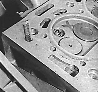
Identification of cylinder head gaskets
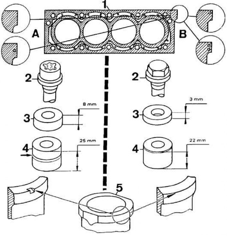
A - the type currently used,
B - type used in some models of early years of production,
1 - cylinder head gasket, 2 - cylinder head bolt, 3 - pads for cylinder head bolts, 4 - spacer near the coolant pump, 5 - cylinder liner
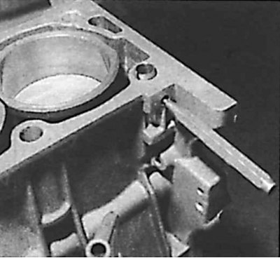
1. Remove the flanges holding the cylinder liners.
2. Using puller 8.0134 L, pull out the cylinder head setting pin on the left side. Set the pin in the top position by inserting a 5 mm pin punch.
3. Check if the second pin is installed on the right.
4. Install the cylinder head gasket with the projection towards the clutch. The thickness of the new gasket is 1.2 mm in engines with an unrefined cylinder head and 1.4 mm in engines after regrinding the head, indicated by the symbol R in front of the #10 bolt. The 1.4 mm thick gasket is marked with a special notch on the ledge (see fig. Identification of cylinder head gaskets).
5. Insert the plastic filter into its seat.
6. Install the cylinder head.
7. Pull out the punch.
8. Clean and lubricate the threads of the ten bolts, insert them together with the washers into the appropriate holes. A bolt fitted with a spacer sleeve is number 8 according to the tightening order.
10. Pre-tighten bolts to 80 Nm in sequence (see fig. The order of tightening the cylinder head bolts).
11. Raise the engine and install the two bolts of the right engine bracket in the cylinder head. Tighten bolts to 20 Nm.
12. Loosen the right engine bracket bolt in the cylinder block.
13. lower the engine (the right upper bracket must be on the elastic support).
14. Tighten the nut of the right engine bracket in the cylinder block and the nut of the coupling clamp to 35 Nm.
15. Completely loosen the cylinder head bolt No. 1, tighten it to a torque of 20 Nm. Use sleeve 8.0154 and tighten the bolt by 120° (hex bolt) or at an angle of 300° (Torx bolt).
16. Repeat these operations for each of the remaining bolts in the order shown.
17. Check valve clearance and adjust if necessary.
18. Install the cylinder head cover.
19. Install the oil gauge guide and diagnostic connector.
20. Attach the oil filler neck to the intake manifold.
21. Fix the parts of the exhaust system.
22. Connect the accelerator cable, coolant lines, fuel lines and electrical connectors.
23. Install the camshaft drive belt.
24. Pour coolant into the cooling system.
25. If a new camshaft drive belt is installed after the engine has cooled down, the tension must be readjusted.
26. Tighten cylinder head (additional operation, only necessary if hex head bolts are used). For this you should:
- remove the cylinder head cover;
- completely loosen the fastening bolt No. 1 and tighten it to a torque of 20 Nm;
- use a bushing and tighten the bolt through an angle of 120°;
- repeat these steps for each of the other bolts in the order shown.
27. Check valve clearance and adjust if necessary.
28. Install the cylinder head cover.
29. Tighten bolt for right engine bracket in cylinder block to 20 Nm. Do not tighten the cylinder head fasteners any further.