



A burnt or defective cylinder head gasket is determined by the following signs:
- to reduce engine power;
- when the coolant level drops, white steam comes out of the exhaust pipe;
- to reduce the engine oil level;
- by the presence of coolant in the engine oil: the oil turns grey and foams. At the same time, the oil level rises;
- by the presence of motor oil in the coolant;
- by the intense release of bubbles from the coolant;
- by reducing compression in two adjacent engine cylinders.
Removal
TU3JP engine
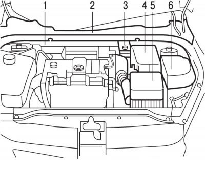
Figure 3.1. Location of units and components in the engine compartment with the TU3JP engine: 1 - plastic crossbar of the amplifier; 2 - plastic windshield deflector; 3 - brake fluid reservoir; 4 - battery; 4 - air filter with air pipe and resonator; 6 - decorative cover of the fuse box
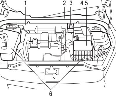
Figure 3.2. Location of units and components in the engine compartment with the TU5JP4 engine: 1 - plastic crossbar of the amplifier; 2 - plastic windshield deflector; 3 - brake fluid reservoir, 4 - battery; 5 - air filter with air pipe and resonator; 6 - decorative cover of the fuse box
Remove and set aside the feed tank 3 (see figure 3.1, 3.2) with brake fluid.
Remove the windshield wiper arms.
Attention! When installing the cylinder head, it is necessary to use new mounting bolts. All clamps and clips that are damaged or cut during removal must be replaced with new ones when installing the cylinder head. When replacing the cylinder head, fill the cooling system with fresh coolant. Before removing the cylinder head, make sure all hoses, lines and electrical connectors are disconnected from it. Turn off the ignition and disconnect the ground wire from the battery.
Remove the plastic windshield deflector 2.
Remove the plastic cross member of the amplifier 1.
Remove the air filter, air duct and resonator 5 as an assembly.
Remove the attachment drives.
Protect the lower front windshield stop with a piece of door weatherstrip.
Remove the mounting clamps, disconnect and move aside the connectors and wiring harnesses that pass near the cylinder head.
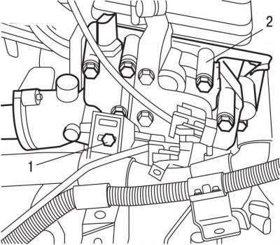
Figure 3.9. Location of the bolt (1) securing the wiring harness to the coolant outlet block (2)
Remove bolt 1 (figure 3.9) harness support fasteners and move the harness away from the coolant outlet block 2.
Disconnect the pipes from the heater radiator.
Using a special tool, remove fuel from the fuel rail.
Release the snap-on fasteners and disconnect the fuel supply pipes adjacent to the cylinder head.
Using special tools, secure the camshaft and flywheel.
Remove the intake pipe of the exhaust system.
Remove the timing belt.
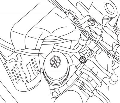
Figure 3.10. Location of the bolt (1) securing the oil level indicator tube
Remove bolt 1 (figure 3.10) oil level indicator tube mounts and remove the upper part of the tube.
Unscrew the nuts and remove the cylinder head cover.
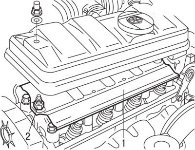
Figure 3.11. Location of spacer (1) and deflector (2) under the cylinder head cover
Remove spacers 1 (figure 3.11) and deflector 2.
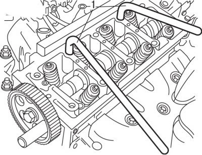
Figure 3.12. Using keys (1) to remove the cylinder head
In the reverse order of tightening, in a spiral, starting with the outer bolt, gradually loosen and then completely unscrew the cylinder head mounting bolts (figure 3.12).
Remove the cylinder head mounting bolts.
Remove the rocker arm mounting ramp.
Install the levers into the cylinder head holes (figure 3.12) and, pressing on them, separate the head from the cylinder block.
Remove the cylinder head and place it on a soft surface.
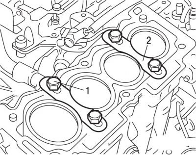
Figure 3.13. Installing the clamping brackets (2) and bolts (1) for fastening them to the cylinder block of the TU3JP engine made of aluminum alloy
On the TU3JP engine cylinder block made of aluminum alloy, install on the clamping brackets 2 (figure 3.13) to fix the cylinder liners and secure them with bolts 1.
Engine TU5JP4
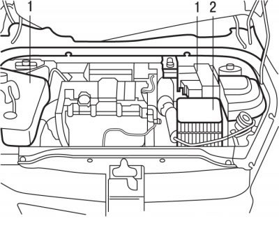
Figure 3.14. Location of decorative covers (1) and cover (2) of the air filter with air duct and resonator in the engine compartment with the TU5JP4 engine
Remove decorative covers 1 (figure 3.14).
Remove the air filter, air duct and resonator 2 as an assembly.
Disconnect the terminals from the battery.
Drain the coolant from the engine cooling system.
Remove the accessory drive belt.
Remove the pulley from the crankshaft.
Support the power unit by placing a support stand under the engine.
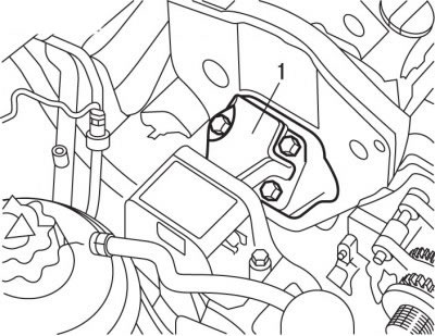
Figure 3.15. Location of the right engine support (1)
Remove the right support 1 (figure 3.15) engine assembly.
Remove the upper and lower timing belt covers.
Remove the top portion of the oil level indicator tube.
Remove the catalytic converter.
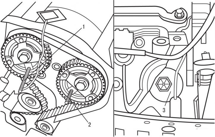
Figure 3.16. Locations for installing special devices for fixing the intake (1) and exhaust (2) valve camshafts and the flywheel (3)
Use special tools to secure the intake and exhaust camshafts and the flywheel (figure 3.16).
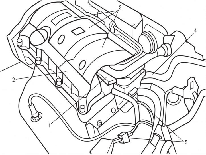
Figure 3.17. Location of the compact ignition coil block: 1 - compact ignition coil block; 2 - lid; cylinder heads; 3 - decorative cover; 4 - air conditioning system heat exchanger tubes; 5-pin connectors
Remove the decorative cover 3 (figure 3.17) and a block of compact ignition coils 1.
In the reverse order of tightening, in a spiral, starting with the outer bolt, gradually loosen and then completely unscrew the bolts securing each cylinder head, just as when tightening the bolts.
Remove cylinder head cover 2.
Disconnect the air conditioning system heat exchanger pipe.
Release the clips and disconnect the contact connectors 5.
Using a special pump, relieve the pressure and remove fuel from the fuel rail.
Disconnect the intake manifold pressure sensor, fuel supply and return pipes, and clutch cable from the air duct.
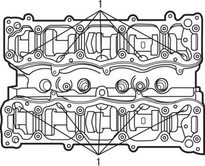
Figure 3.18. Location of bolts (1) on the inner sides of the cylinder heads
Sequentially, starting from the outside, in a spiral, unscrew the bolts located on the inner sides of the cylinder heads 1 (figure 3.18).
Remove the bolts securing each cylinder head.
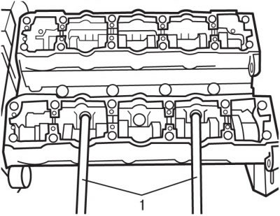
Figure 3.19. Using levers (1) to separate the head from the cylinder block of the TU5JP4 engine
Install levers 1 into the holes of the cylinder head (figure 3.19) and, pressing on them, separate the heads from the cylinder block.
Remove the cylinder head and place it on a soft surface.
Preparing the head for installation
The mating surfaces of the cylinder head and block must be completely clean. To clean them, use a hard plastic or wooden scraper. When cleaning, be careful as the aluminum alloy is very easy to damage. Make sure that carbon deposits do not get into the lubrication and cooling system channels. This is especially important for the lubrication system, as carbon deposits can block the supply of oil to engine parts. Clean the channels if necessary.
Check the mating surfaces of the cylinder head and block: they should not have any nicks, deep scratches or other damage. Minor defects can be removed by mechanical processing. In case of significant defects, parts are subject to replacement.
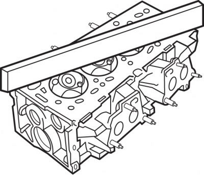
Figure 3.20. Measuring the non-flatness of the cylinder head mating surface
Using a metal ruler and feeler gauge, check the mating surfaces for flatness (figure 3.20).
If the deviation from flatness exceeds 0.05 mm, the head must be re-ground. The height of the cylinder head of the TU3JP engine after mechanical processing must be at least 111.00 mm.
Clean the threads of the cylinder head bolt holes in the block using an M10xM150 tap.
Clean the bolt holes in the block. Driving a bolt into an oil filled hole can cause the block to burst due to hydraulic pressure.
Before reusing the bolts, measure the length of the bolts to the base of the head, which should be 176.5 mm for the TU3JP engine and 122.6 mm for the TU5JP4 engine.
Make sure the camshaft rotates freely in the bearings.
Installation
TU3JP engine
On the TU3JP engine cylinder block made of aluminum alloy, unscrew the bolts and remove the clamping brackets 2 (see Figure 3.13).
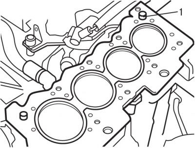
Figure 3.21. Location of guide bushings (1) in the cylinder block of the TU3JP engine
Check that the guide bushings 1 (figure 3.21) installed in the cylinder block.
Remove the new cylinder head gasket from its packaging immediately before installation.
Place the gasket on the guide bushings with the "Oben" lettering facing the head.
Install the cylinder head with the camshaft timing belt pulley fixed.
Install the rocker arm mounting ramp in place.
Apply a thin coat of molybdenum-based lubricant to the cylinder head bolt threads, insert the bolts and tighten them hand-tight.
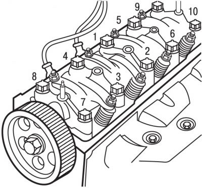
Figure 3.22. Tightening sequence of cylinder head bolts on the TU3JP engine
In the sequence shown in the figure 3.22, tighten the cylinder head mounting bolts in two stages:
- 1st - tighten to 20 Nm;
- 2nd - turn to an angle of 240°.
There is no need to further tighten the cylinder head mounting bolts.
Install the timing belt to drive the gas distribution mechanism.
Install the accessory drive belt.
Adjust the rocker arms.
Fill with coolant and bleed it.
Further installation of the engine is carried out in the reverse order of removal.
Engine TU5JP4
Check that the guide bushings 1 (see figure 3.21) installed in the cylinder block.
Remove the new cylinder head gasket from its packaging immediately before installation.
Place the gasket on the guide bushings with the "Oben" lettering facing the head.
Install the cylinder heads with the camshaft timing belt pulleys fixed in position.
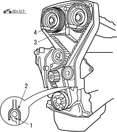
Figure 3.23. When installing the cylinder head, the camshaft timing belt pulleys must be fixed in a certain position with special devices (3 and 4), and the stiffening rib (2) in the lower part of the timing belt casing must fit tightly into the seal holder (1)
Install stiffener 2 (figure 3.23) at the bottom of the timing belt cover so that it fits tightly into the seal holder 1.
Apply a thin coat of molybdenum-based lubricant to the cylinder head bolt threads, insert the bolts and tighten them hand-tight.
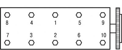
Figure 3.24. Tightening sequence of cylinder head bolts on the TU5JP4 engine
In the sequence shown in the figure 3.24, tighten the cylinder head mounting bolts in two stages:
- 1st - tighten to 20 Nm;
- 2nd - turn it to an angle of 260°.
Fill the cavities located under the hydraulic valve lifters with fresh engine oil.
Install the cylinder head covers, cleaning the gaskets and the surfaces on which they are installed. The head covers are equipped with composite gaskets that can be used multiple times. Minor damage to gaskets can be partially repaired using a special AUTOJOINTOR sealant.
Further installation of the cylinder head is carried out in the reverse order of removal.
Connect the battery.
Fill with coolant and bleed it.
Perform the engine management system computer initialization operation.