
Removing
Attention! Chalk, marker or paint mark the direction of rotation of the toothed belt. If the toothed belt rotates in the opposite direction during installation, this will lead to its destruction.
TU3JP engine
Disconnect the wire from the negative battery terminal.
Remove the accessory drive belt.
Support the engine with a jack through a wooden spacer so that the weight of the engine is supported by the jack.
Remove the right upper engine mount.
Remove the accessory drive pulley from the crankshaft.
Remove the toothed belt covers.
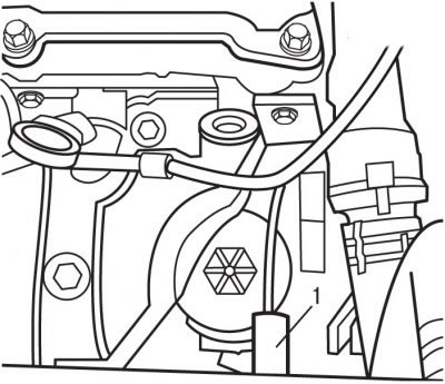
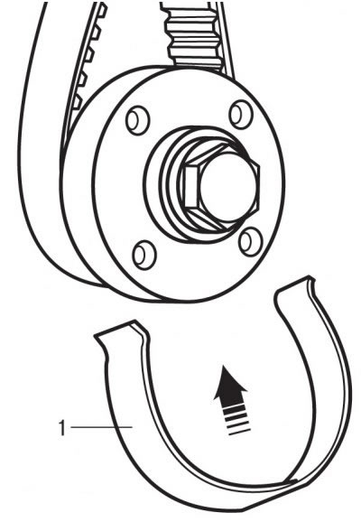
Pic. 3.35. Using a special tool (1) for fixing the engine flywheel from turning
Turning the crankshaft of the engine in the direction of working rotation, set the piston of the 1st cylinder to TDC with a special tool 1 (pic. 3.35), fixing the engine flywheel from turning.
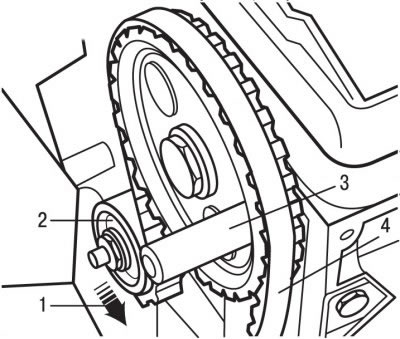
Pic. 3.36. Elements for fixing and tensioning the toothed belt: 1 - nut; 2 - tension roller; 3 - special pin; 4 - toothed belt
Fix the camshaft with a special pin 3 (pic. 3.36).
Pic. 3.33. Bottom bolt location (1) alternator mounts and bolts (2) belt tension adjustment on TU5JP4 engine
Pic. 3.37. Mechanism for adjusting the tension of the toothed belt of the TU3JP engine: 1 - adjusting eccentric with a hexagonal head; 2 - mark of the final tension of the belt; 3 - belt pretension mark; 4 - pointer
Loosen the torque of the nut 1 (see fig. 3.33), holding the tension roller 2, then using the adjusting eccentric 1 (pic. 3.37) move the tension roller horizontally 6 clicks towards the water pump, as a result of which the tension of the toothed belt will loosen.
Remove toothed belt 4 (see fig. 3.36).
Attention! Do not rotate the engine crankshaft with the toothed belt removed, as the pistons may hit the valves.
Engine TU5JP4
Disconnect the wire from the negative battery terminal.
Remove the right front wheel.
Remove the engine splash shield.
Remove the accessory drive belt.
Unscrew the central bolt and remove the accessory drive belt pulley from the crankshaft.
Support the engine with a jack with platform and stands so that the weight of the engine is supported by the jack.
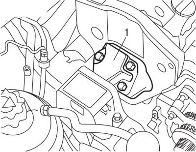
Pic. 3.15. Location of the right support (1) engine
Turn out bolts and remove the right support 1 (see fig. 3.15) assembled engine.
Remove the upper and lower toothed belt covers.
Turning the crankshaft of the engine in the direction of working rotation, set the piston of the 1st cylinder to TDC and fix the engine flywheel from turning with a special tool.
Fix the camshafts with special pins.
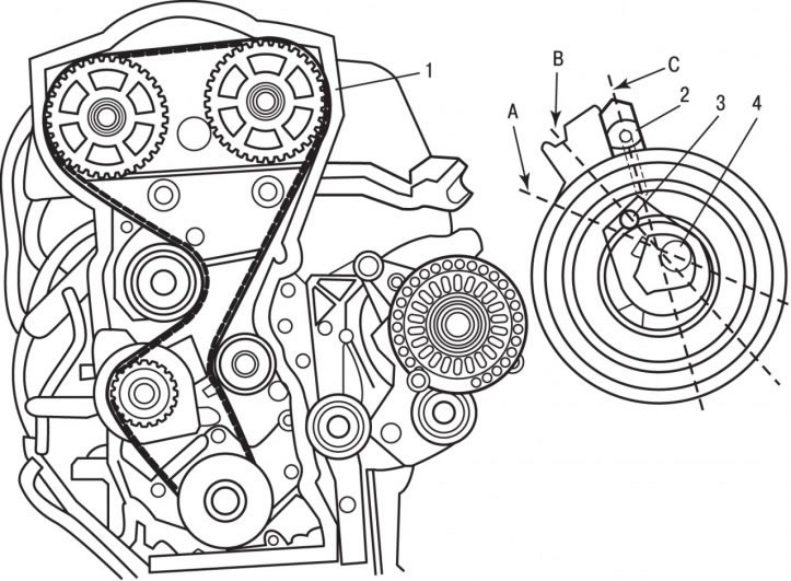
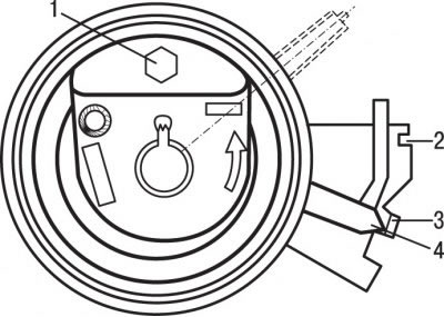
Pic. 3.38. Positions of the toothed belt tensioner on the TU5JP4 engine: 1 - toothed belt; 2 - pointer; 3 - hex head; 4 - a bolt of fastening of a tension roller; A - the position of the maximum weakening of the tension of the toothed belt; B - the position of the normal tension of the toothed belt; C - the position of the maximum tension of the toothed belt
Remove bolt 4 (pic. 3.38) fastening of a tension roller of a toothed belt.
For the hexagonal head 3, turn the tension roller clockwise until the pointer aligns with mark A, while the toothed belt will loosen the tension as much as possible. Lock the tension roller in this position.
Attention! Do not turn the toothed belt tensioner a full turn.
Remove the toothed belt.
Attention!
- 1. Do not twist or bend the toothed belt. Do not expose the toothed belt to oil, coolant or fuel.
- 2. If toothed belt teeth are chipped, the water pump, oil pump, or camshaft may be stuck.
- 3. A broken toothed belt while the engine is running can be caused by the pistons hitting the valves, causing the valves to deform.
- 4. Check valve clearances. On deformed valves, they will be much larger than required.
- 5. If the outer surface of the toothed belt is significantly worn or split, check the condition of the idler pulley tread. If wear or damage is found on only one side of the belt, check the toothed belt guide and the alignment of the toothed belt pulleys. If there are any defects on the toothed belt, it must be replaced.
- 6. The previously removed belt is installed in accordance with the marked marks.
Note. If it is necessary to rotate the camshaft with the toothed belt removed, the crankshaft must not be in the TDC position of the piston of the first cylinder, as the pistons may hit the open valves and the engine will be damaged. To do this, mark the position and turn the crankshaft a quarter of a turn to one side or the other.
Installation
TU3JP engine
Check up smoothness and uniformity of rotation of a tension roller.
Check that the flywheel and camshaft pulley are locked in position.
Install the new belt while holding the belt tightly taut between the crankshaft pulley and the camshaft pulley in the following order:
- crankshaft pulley;
- camshaft pulley;
- water pump drive pulley;
- tension roller.
Remove the special tool and pin that secures the flywheel and camshaft from turning.
For the hex head of the adjusting eccentric 1 (see fig. 3.37) turn the tension roller counterclockwise so that the pointer 4 is aligned with the mark 2. While holding the roller in this position, tighten the nut 1 (see fig. 3.36) torque 20 Nm.
Turn the engine crankshaft 10 revolutions clockwise until the piston of the 1st cylinder is set to TDC.
Fix the engine flywheel from turning with a special tool 1 (see fig. 3.35).
With the correct installation of the gas distribution mechanism, special pin 3 (see fig. 3.36) should lock the camshaft pulley.
While holding roller 2 in the same position, loosen nut 1.
For hex head 1 (see fig. 3.37) adjusting eccentric, turn the tension roller clockwise so that pointer 4 is aligned with mark 2 of the final belt tension.
While holding the roller in this position, tighten the nut 1 (see fig. 3.36) torque 20 Nm.
Remove the special device that secures the flywheel from turning.
Check pointer position 4 (see fig. 3.37).
If pointer 4 is not aligned with mark 2 of the final belt tension, it is necessary to loosen the nut of the tension roller and repeat the operations for tensioning the toothed belt.
Turn the engine crankshaft two turns clockwise until the piston of the 1st cylinder is at TDC.
Check the correct installation of the timing mechanism by fixing the flywheel and camshaft pulley in a certain position using a special tool 1 (see fig. 3.35) and pin 3 (see fig. 3.36). Otherwise repeat operations on a tension of a gear belt.
Install the toothed belt guards.
Reinstall the accessory drive pulley and secure it with the bolt to 25 Nm.
Install the right upper engine mount and accessory drive belt.
Connect the wire to the negative battery terminal.
Engine TU5JP4
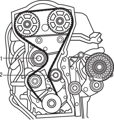
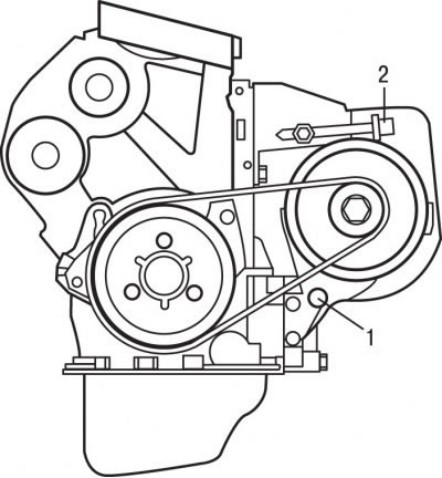
Pic. 3.39. Location of guide rollers (1 and 2) timing belt on TU5JP4 engine
Make sure that guide rollers 1 and 2 (pic. 3.39) rotate smoothly and evenly.
There are three marks C, D and E on the reverse side of the toothed belt (see fig. 3.38), located opposite teeth 1, 52 and 72. The marks are strokes applied with white paint on the back of the toothed belt opposite the corresponding teeth.
Install the toothed belt.
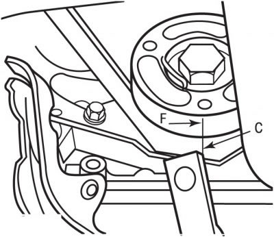
Pic. 3.40. Label Alignment (WITH) toothed belt with groove (F) crankshaft pulley
Align mark C of toothed belt with groove F (pic. 3.40) crankshaft pulley.
Pic. 3.41. Installation direction of the special tool (1) on the crankshaft timing belt pulley
To maintain the toothed belt, install the special tool 1 on the crankshaft pulley (pic. 3.41).
For hexagon 3 (see fig. 3.38) turn the tension roller counterclockwise until pointer 2 is set to position C for the maximum tension of the toothed belt, and in this position tighten the tension roller mounting bolt to a torque of 10 Nm.
Remove the special devices that fix the flywheel and camshaft pulleys from turning.
Turn the engine crankshaft four turns clockwise until the piston of the 1st cylinder is set to TDC and with a special tool, fix the engine flywheel from turning.
Loosen the idler pulley bolt.
For hexagon 3 (see fig. 3.38) turn the tension roller counterclockwise until pointer 2 is set to position B of the normal toothed belt tension, and in this position tighten the tension roller mounting bolt to 22 Nm.
Remove the special device that secures the flywheel from turning.
Turn the engine crankshaft two revolutions clockwise until the piston of the 1st cylinder is at TDC and check the position of the tension roller, which may deviate by±2.0 mm in relation to the position in which it was previously tightened. Otherwise, repeat the operations to adjust the toothed belt tension.
Check the correct installation of the timing mechanism by fixing the flywheel and camshaft pulleys in a certain position using special tools. Otherwise repeat operations on a tension of a gear belt.
Remove the special devices that fix the flywheel and camshaft pulleys from turning.
Install the toothed belt guards.
Install the accessory drive belt pulley on the crankshaft and secure it with a bolt, tightening it to 25 Nm.
Install the accessory drive belt and adjust its tension.
Install the right engine mount, engine mudguard and right front wheel.
Connect the wire to the negative battery terminal.