



Recommendations for engine removal
Please read this section carefully before you begin.
If the engine is removed for repair, it is necessary to select a location for the work, provide space for servicing and storing spare parts. It is recommended that repairs be carried out at a service station or in a garage with a level, horizontal floor covered with a clean, hard surface.
Before removal, clean off any dirt and wash the engine and engine compartment. To remove, use a lifting mechanism that allows you to safely lift the power unit.
If you are removing the power unit for the first time, you should invite an experienced specialist. Some jobs should be done with an assistant.
All clamps and clips that are damaged or cut during engine removal are replaced with new ones during engine assembly.
Depending on the year of manufacture and the vehicle's configuration, electrical wires, pipes, and hoses may be located differently in the engine compartment. Therefore, before disconnecting electrical connectors and disconnecting pipes or hoses, it is recommended to mark them with adhesive tape.
The engine is removed forward together with the gearbox.
The drained coolant must be collected and disposed of.
Removal
Place the vehicle on a two-post lift.
Open the hood to the service position and secure it with the bolt and nut system.
Drain the coolant.
Drain the oil from the gearbox.
Drain the engine oil from the engine.
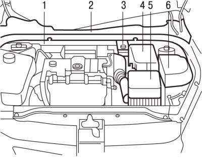
Figure 3.1. Location of units and components in the engine compartment with the TU3JP engine: 1 - plastic crossbar of the amplifier; 2 - plastic windshield deflector; 3 - brake fluid reservoir; 4 - battery; 4 - air filter with air pipe and resonator; 6 - decorative cover of the fuse box
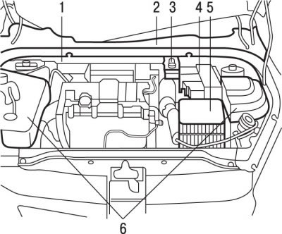
Figure 3.2. Location of units and components in the engine compartment with the TU5JP4 engine: 1 - plastic crossbar of the amplifier; 2 - plastic windshield deflector; 3 - brake fluid reservoir, 4 - battery; 5 - air filter with air pipe and resonator; 6 - decorative cover of the fuse box
Remove and set aside the feed tank 3 (figure 3.1, 3.2) with brake fluid.
Remove the windshield wiper arms.
Remove the plastic windshield deflector 2.
Remove decorative cover 6.
Remove the plastic cross member of the amplifier 1.
Remove the air filter, air duct and resonator 5 as an assembly.
Remove the right wheel arch mudguard.
Remove the battery 4 and its bracket.
Remove the front bumper.
Remove the headlights.
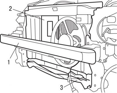
Figure 3.3. Location of the front panel cross member (1), the cooling cassette assembly (2) together with the radiator and the lower front panel cross member (3)
Remove the front panel cross member 1 (figure 3.3).
Remove the cooling cassette assembly 2 together with the radiator.
Move aside and secure the air conditioning radiator.
Remove the lower cross member of the front panel 3.
Do not allow the sound signal to hang on its wire.
Caution! Do not open the air conditioning system cooling circuit.
Relieve the pressure in the fuel rail using the SCHRADER valve.
Disconnect the wiring harnesses and fuel supply line from the engine.
Remove the catalytic converter.
Remove the accessory drive belt.
Remove the air conditioning compressor mounting bolts and move it to the side without disconnecting the pipes from it.
Remove the air conditioning compressor bracket.
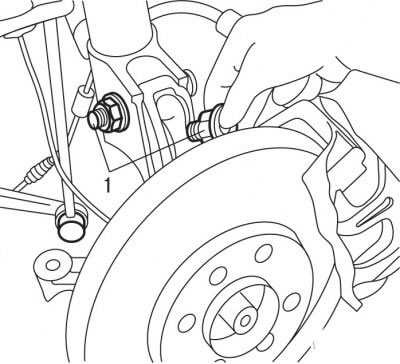
Figure 3.4. Location of bolts (1) securing the steering knuckle to the front suspension strut
Remove bolts 1 (figure 3.4) fastening the steering knuckle to the front suspension strut.
Remove the front suspension ball joint pin from the steering knuckle.
Release the ABS sensor from the mounting brackets.
Move the wheel hub assembly away from the vehicle.
Remove the wheel drive shafts.
Replace and secure the wheel hub.
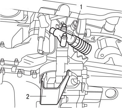
Figure 3.5. Location of the bolts for fastening the clutch slave cylinder (1) and the shock absorber (2) of the subframe
Unscrew the bolts and remove the slave cylinder 1 (figure 3.5) clutch.
Remove the shock absorber 2 from the engine subframe.
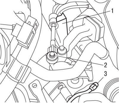
Figure 3.6. Location of the support (1) of the traction system, fingers (2) of the gearshift mechanism and nuts (3) of the "ground" wire attachment
Remove fingers 2 (figure 3.6) gear shift mechanism.
Remove support 1 of the traction system.
Loosen the clamps and remove the coolant supply hoses to the heater radiator.
Unscrew nut 3 and disconnect ground wire 3.
Release the engine electrical wiring harnesses from the clamps at the computer and gearbox level.
Place the jack and platform under the power unit and secure the platform and engine mounting hardware at the following points:
- in place of the anti-roll bar link;
- in place of the catalytic converter mounting bolt on the engine block;
- on the air conditioner compressor bracket mounts;
- instead of the catalytic converter mounting bolt on the cylinder block.
Raise the jack with the platform so that the weight of the power unit is supported by the jack.
Remove the right engine mount bracket.
Remove the elastic mount of the gearbox.
Make sure all electrical wires, hoses, pipes and lines are disconnected from the engine.
Remove the power unit, being careful not to touch any surrounding components.
If necessary, disconnect the gearbox from the engine.
Installation
The engine is installed in the reverse order of removal, taking into account the following.
Replace with new self-locking nuts and bolts that were tightened by turning them to a certain angle, as well as sealing rings and gaskets.
Check for the presence of centering bushings that determine the relative position of the engine and gearbox.
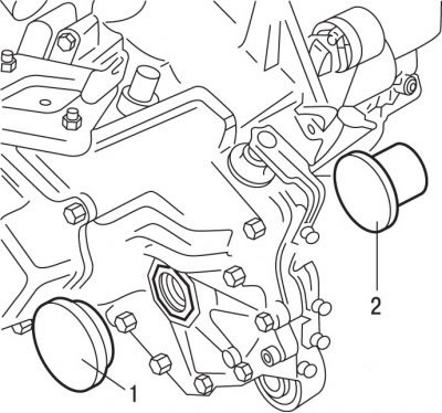
Figure 3.7. Using mandrels (1 and 2) to replace differential seals
Using mandrels 1 and 2 (figure 3.7) replace the differential seals. Before installing the sealing rings, fill the space between the working edges of the ring with grease.
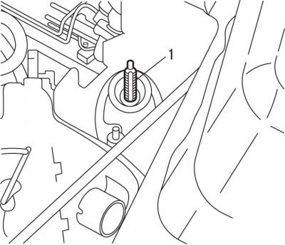
Figure 3.8. Location of the axle (1) of the left engine mount, on which a thin layer of SPAGRAH grease must be applied
Apply to axis 1 (figure 3.8) apply a thin layer of SPAGRAH grease to the left engine mount and install the power unit in place.
Tighten the left engine mount mounting nut to 65 Nm.
Install the right engine mount bracket.
Further installation of the engine is carried out in the reverse order of removal, taking into account the following.
Install the engine mount torque arm.
Install the accessory drive belt.
Install the wheel drive shafts.
Fill the gearbox and engine with oil.
Install the front bumper and headlights.
Fill with coolant and bleed it.
Connect the battery.