



Table of contents: Removal 🠇 Installation 🠇
When removing and installing the power unit at Peugeot service centers, the following special tool is used:
- nAUDER type load stabilizer;
- mandrels for installing seals at the bridge outlet — 0317-T/ 0317-U;
- flywheel stopper - 0188-F;
- ball Joint Retainer Remover - 0317-AC;
- pulley puller - 0188-P;
- set of plugs - 0188-T;
- mandrel for removing the gearbox suspension axle - 0317-AB.
Removal
Remove the power unit with the DW10 TD engine in the following order:
Note: The power unit is removed upwards.
- disconnect the negative battery cable;
- install the retaining rods on the front suspension springs;
- remove the mudguards under the power unit;
- drain the cooling system;
- drain the oil from the gearbox and engine;
- remove the front wheels, placing the car on supports;
- remove mudguards;
- remove the CV joints on both sides;
- remove the accessory drive belt;
- disconnect the inlet pipe from the exhaust manifold;
Caution! Be careful when removing the exhaust pipe to avoid damaging the flexible link (bellows), which cannot withstand the torsional, tensile or bending loads that may occur when dismantling one of the powertrain suspension components.
- remove the accessory drive belt eccentric roller;
- without disconnecting the pipes, move aside and secure the air conditioning compressor;
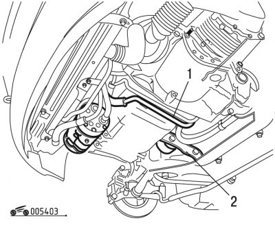
Figure 4.3. Removing the power steering hose: 1 - power steering hose; 2 - engine mount jet bracket
[Information posted on the website: PeugeotBook.ru]
- release hose 1 (figure 4.3) power steering;
- remove the clutch housing guard;
- secure the flywheel with a stopper;
- remove the accessory drive pulley using a tool;
- remove the engine mount jet bracket 2;
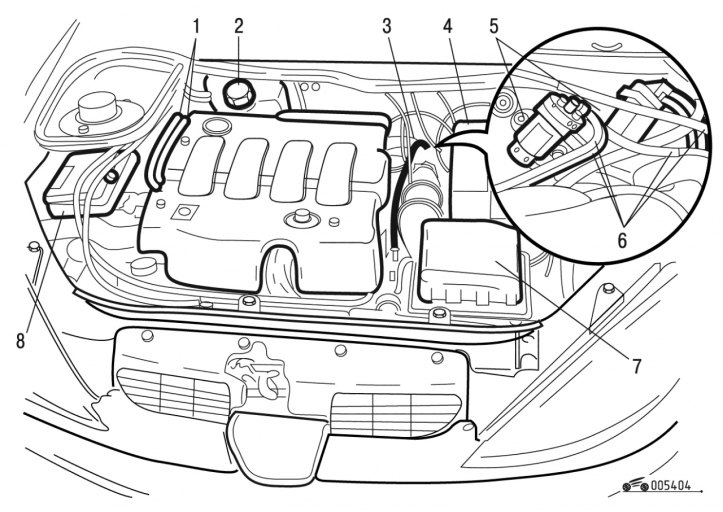
Figure 4.4. Removing the battery and expansion tank: 1 - fuel supply pipe fittings; 2 - expansion tank; 3 - brake booster hose; 4 - battery stand; 5 - electromagnetic valves; 6 - tubes; 7 - knot; 8 - electronic unit
- remove decorative cover 8 (figure 4.4);
- move node 7 aside;
- disconnect and move aside the wire harnesses and cables leading to node 7;
- remove the battery;
- disconnect and move aside the wire harnesses adjacent to the battery compartment;
- remove the battery holder 4;
- remove the support of the node 7;
- remove expansion tank 2 of the cooling system;
- remove the cooling system radiator;
- protect the capacitor with a piece of hard cardboard;
- mark the location of the tubes 6 on the solenoid valves 5;
- remove the solenoid valve support;
- move the brake booster hose to the side;
- move aside the electronic unit 8 with the bracket;
- move aside the fitting 1 of the fuel supply pipes;
- close the holes with plugs;
- move the wiring harness aside;
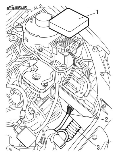
Figure 4.5. Removing the fuse box cover: 1 - lid; 2 - wiring harness; 3 - air ducts
- remove cover 1 (figure 4.5) fuse box;
- remove air duct 3;
- disconnect and remove the electrical fuse box wiring harnesses;
- disconnect and move aside the clutch drive;
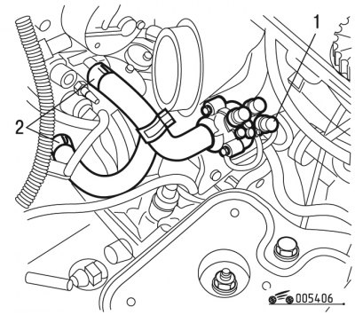
Figure 4.6. Assembled heater: 1 - heater; 2 - heat exchanger pipes
- move pipes 2 to the side (figure 4.6) heat exchanger;
- disconnect the ground wire from the side member;
- move heater 1 assembly aside;
- disconnect the transmission control rod using a tool;
Caution! Remove the stopper with a pushing motion, without creating a lever, so as not to deform the rods.
- without disconnecting the pipes, move aside and secure the power steering pump;
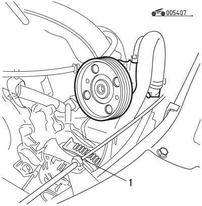
Figure 4.7. Removing the generator: 1 - generator
- remove generator 1 (figure 4.7);
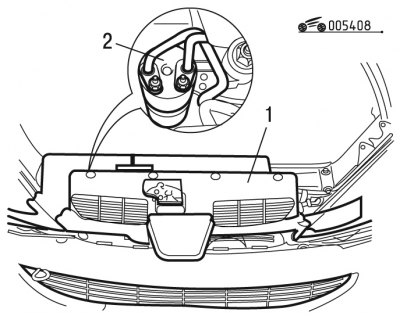
Figure 4.8. Air conditioning system reservoir: 1 - node; 2 - tank
- remove node 1 (figure 4.8);
- release the air conditioning system tubes from the clamps (front right side member);
- move the tank on the outlet pipe without disconnecting the pipes;
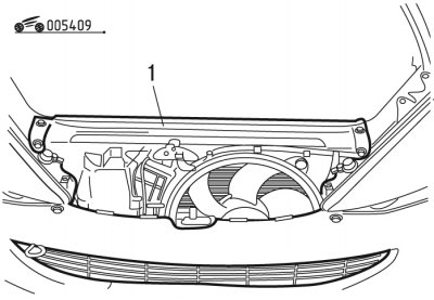
Figure 4.9. Removing the unit at the front of the vehicle: 1 - node
- remove node 1 (figure 4.9);
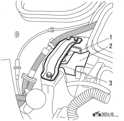
Figure 4.10. Removing the right engine mount bracket: 1 - stop; 2 - right bracket; 3 - jumper
- remove jumper 3 (figure 4.10);
- remove stop 1;
- remove the right engine mount bracket 2;
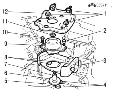
Figure 4.11. Removing the power unit: 1, 2, 4, 8, 10 - bolts; 3, 5 - calipers; 6 - axis; 7 - spacer; 9 - support cushion; 11 - nuts; 12 - battery support
- unscrew bolts 1 (figure 4.11) battery support mounts;
- remove support 12 of the battery;
- unscrew nuts 11 of the gearbox support axle and remove them with washers;
- unscrew the bolts 10 of the pillow;
- remove elastic cushion 9 of gearbox support;
- unscrew bolts 8;
- remove caliper 3;
- remove spacer 7;
- remove axle 6 using a tool;
- unscrew bolts 4;
- remove caliper 5;
- remove the power unit upwards.
Installation
Install the power unit with the DW10 TD engine in the following order:
- replace the self-locking nuts and clamps of the exhaust system;
- using mandrels, replace the seals at the gearbox outlet, having first filled the space between their edges with grease;
- install the power unit in place;
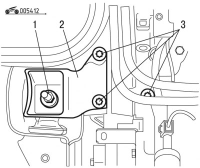
Figure 4.12. Installing the engine support bracket: 1, 3 - bolts; 2 - bracket
- install right bracket 2 (figure 4.12) engine mounts;
- tighten bolts 1 and 3 to 45 Nm;
- install stop 1 (see figure 4.10) and tighten the mounting bolts to a torque of 32 Nm;
- install jumper 3, tightening the mounting bolts to a torque of 21.5 N·m;
- install caliper 5 (see figure 4.11), tightening the 4 fastening bolts with a torque of 6 Nm;
- install axle 6 and spacer 7, securing them with bolts to a tightening torque of 5 Nm;
- install the 3rd gearbox axle support, securing it with 8 bolts to a tightening torque of 19 Nm;
- install elastic cushion 9 of gearbox support;
- screw on the gearbox support axle nut, having first installed the washer;
- tighten the bolts 2 pillows (without tightening);
Caution: Center the power unit before tightening the elastic cushion mounting bolts.
- finally tighten bolts 10 to 30 Nm;
- finally tighten nuts 11 to 65 Nm;
- install support 12 battery;
- tighten bolts 1 fastening with a torque of 19 Nm;
- reinstall the generator;
- first tighten the crankshaft pulley mounting bolts to 41 N·m, then tighten the oil filter bolts to 39 N·m;
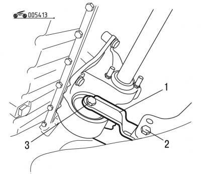
Figure 4.13. Installing the engine suspension reaction arm: 1 - lever; 2, 3 - bolts
- install the reaction lever 1 (figure 4.13) engine mounts;
- tighten bolts 3 to 50 Nm;
- tighten bolts 2 to 35 Nm;
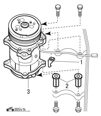
Figure 4.14. Installing the air conditioning compressor: 1 - lock nut; 2 - spacers; 3 - compressor
- make sure that two spacers 2 are in place (figure 4.14);
Caution! Lock nut 1 secures the rear upper part of the compressor.
- install compressor 3 following the installation sequence of the above parts;
- connect the contact connector;
- install front wheel drives on both sides;
- tighten the wheel hub nuts to 325 Nm;
- install the accessory drive pulley;
- use an M16350 tap to tap the internal thread of the crankshaft for the pulley mounting bolt;
- clean the bolt threads with a wire brush, tighten it to 40 Nm and then tighten it to an angle of 50° using a device such as FACOM D360;
- install the pump in accordance with the sequence of installation of the parts;
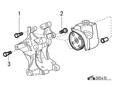
Figure 4.15. Pump installation: 1, 2, 3 - bolts
- tighten bolt 1 (figure 4.15) torque of 25 Nm;
- tighten bolt 3 to 25 Nm;
- tighten bolt 2 to 22 Nm.
Continue installing the power unit in the reverse order of removal.
After installing the power unit, fill the gearbox with oil, and if necessary, the engine, then:
- tighten the wheel bolts to 85 Nm;
- fill the engine cooling system and bleed air from it;
- perform programming of the vehicle's electronic devices.