



Table of contents: Removal 🠇 Installation 🠇
When removing and installing the engine at Peugeot service centers, the following special tool is used:
- traverse - 0102-D
- flywheel stopper - 0188-F;
- hooks for hanging;
- gearbox rod release fork — 0102-G1/-G2;
- mandrel for installing oil seals - 0317-T/-U.
Removal
Remove the power unit with the DW8 engine in the following order:
Note: The power unit is removed upwards.
- set the hood cover to a vertical position using the device;
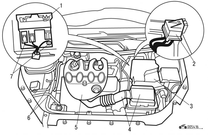
Figure 4.16. Removing the battery: 1 - relay block; 2 - preheating unit; 3 - battery; 4 - air cleaner unit; 5 - decorative cover; 6 - nipples; 7 - bolts
- remove decorative cover 5 (figure 4.16);
- remove block 4 of the air cleaner with air ducts;
- remove battery 3 with tray;
- remove preheating unit 2;
- unscrew two bolts 7;
- remove block 1 relay;
- remove the air filter housing;
- remove the battery tray support;
- disconnect and move aside the 6 fuel supply pipe fittings;
- remove the electronic control unit;
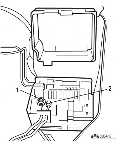
Figure 4.17. Disconnecting the wires: 1, 2 - wires
- disconnect wires 1 and 2 (figure 4.17);
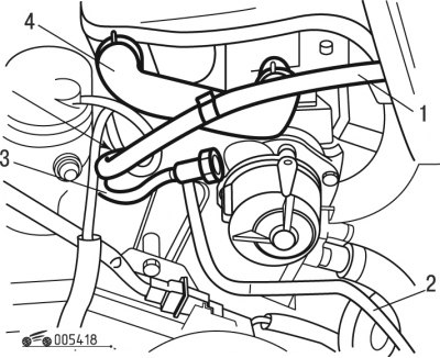
Figure 4.18. Disconnecting the tubes: 1, 2, 3, 4 - tubes
- disconnect tubes 1, 2, 3 (figure 4.18);
- remove the front wheels;
- drain the oil from the gearbox;
- drain the coolant from the cooling system;
- remove mudguards;
- remove the protective screen under the engine;
- remove the front wheel drives from both sides of the vehicle;
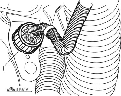
Figure 4.19. Disconnecting the contact connector: 1-pin connector
- disconnect pin connector 1 (figure 4.19) on the inner panel of the left front fender;
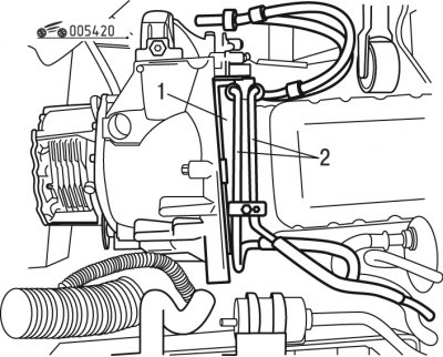
Figure 4.20. Power steering pipes: 1 - tubes; 2 - protective board
- release and move aside tubes 1 (figure 4.20) power steering, passing in the engine area;
- remove the protective board 2;
- disconnect the exhaust pipe from the exhaust manifold side;
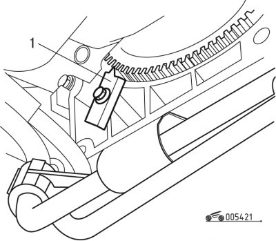
Figure 4.21. Installing the flywheel lock: 1 - retainer
- install clamp 1 (figure 4.21);
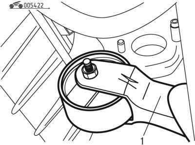
Figure 4.22. Removing the engine mount reaction bracket: 1 - bracket
- remove the jet bracket 1 (figure 4.22) engine mounts;
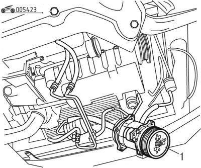
Figure 4.23. Removing the air conditioning compressor: 1 - compressor
- without opening the refrigeration circuit of the air conditioning system, move compressor 1 to the side (figure 4.23);
Caution: Never bend the air conditioning system refrigeration circuit pipes.
- remove the front panel;
- move the power steering pump away without opening the system circuit;
- disconnect and move aside the heat exchanger pipes at the level of the shield;
- disconnect and move aside the brake booster hose;
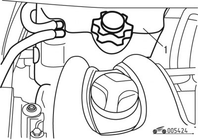
Figure 4.24. Removing the tank: 1 - tank
- move the tank 1 (figure 4.24) along with his pipes;
- move the flexible clutch cable or the clutch slave cylinder to the side;
- disconnect the transmission control rods using the tool;
- cover the air conditioning condenser core tubes with a sheet of heavy-duty cardboard;
- remove the accessory drive belt;
- remove the generator;
- remove the crankshaft pulley;
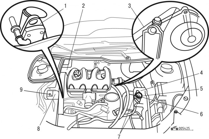
Figure 4.25. Removing parts and assemblies before dismantling the power unit: 1, 3 - lifting brackets; 2, 5, 7 - bolts; 4 - gasket; 6, 9 - nuts; 8 - right bracket
- bring the lifting beam with hooks, hook the hooks onto lifting brackets 1 and 3 (figure 4.25), and then tighten the cables;
- unscrew three bolts 2;
- unscrew nut 9;
- remove the right engine mount bracket 8;
- unscrew nut 6;
- unscrew two bolts 7;
- remove elastic pad 4;
- unscrew the two bolts 5 securing the support;
- remove the caliper;
- disconnect and move aside the wiring harnesses, pipes related to the gearbox or engine;
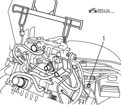
Figure 4.26. Bushing on the engine: 1 - bushing
- remove the power unit upwards, preserving the bushing 1 (figure 4.26).
Installation
Install the power unit with the DW8 engine in the reverse order of removal, while observing the following:
- systematically replace the self-locking nuts and seals at the gearbox outlet using mandrels;
Caution! Before installing the seals, pack the space between the edges with grease.
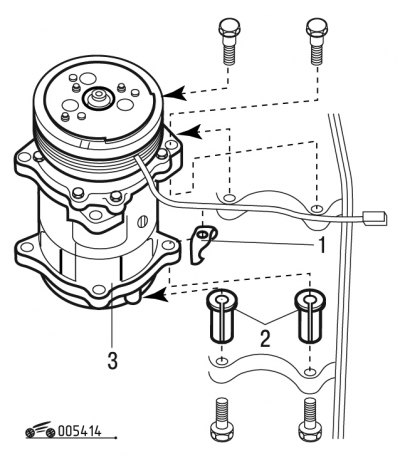
Figure 4.14. Installing the air conditioning compressor: 1 - lock nut; 2 - spacers; 3 - compressor
- install the compressor following the installation sequence of the above parts;
Attention! Lock nut 1 (see figure 4.14) secures the rear upper part of the compressor.
- first tighten the crankshaft pulley bolts to 42 N·m, then tighten the oil filter bolts to 39 N·m;
- carefully observe the routing and attachment points of wire bundles and wiring harnesses;
- bring the gearbox oil level up to normal;
- fill the engine cooling system and bleed air from it;
- perform programming of all electronic devices.