
A gasket of appropriate thickness is installed between the head and the cylinder block. The gasket is made of corrugated sheet metal. The thickness of the cylinder head gasket is selected depending on the amount of protrusion of the pistons above the mating surface.
When removing and installing the cylinder head at Peugeot service centers, use the following special tool:
- auxiliary levers for separating the head from the cylinder block - 0188-L;
- dial indicator support - 0110-H;
- indicator head;
- corner tightening wrench - facom d 360.
Removing
Remove the cylinder head in the following order:
- disconnect the battery;
- remove the decorative cover;
- remove the air cleaner unit with all connections;
- remove the intake air distributor;
- remove the valve tube of the exhaust gas recirculation system;
- remove the vacuum pump;
- drain the coolant from the cooling system;
- remove the diesel fuel filter housing;
- remove the fastening clamps, disconnect and set aside the contact connectors and wiring harnesses passing in the area of the cylinder head;
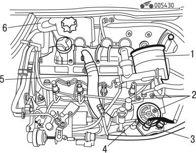
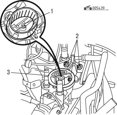
Pic. 4.30. Preliminary removal of components and parts: 1 - diesel fuel filter; 2, 4 - bolts; 3 - coolant outlet block; 5 - tubes; 6 - expansion tank
- remove filter 1 (pic. 4.30) diesel fuel assembly;
- unscrew bolts 4;
- unscrew bolts 2;
- remove block 3 coolant outlet;
- lift handset 5;
- remove expansion tank 6;
- remove the union for connection with the heat exchanger on the cylinder head;
- remove the timing belt;
- remove the camshaft pulley;
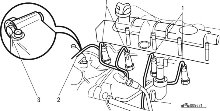
Pic. 4.31. Disconnecting the fuel lines: 1 - fuel lines; 2 - fuel return pipe; 3 - bolt
- remove fuel lines 1 (pic. 4.31) high pressure;
- unscrew bolt 3;
- remove tube 2 fuel return;
- disconnect a reception pipe of system of release of the fulfilled gases;
- unscrew, sequentially moving in a spiral, the bolts of the cylinder head, starting with the outer bolt;
- swing and tear off the cylinder head with levers;
- remove the cylinder head and its gasket;
- clean the sealing surfaces on the camshaft using an approved cleaner;
Attention! It is forbidden to use abrasive or piercing-cutting devices and tools. The surfaces to be joined must not show signs of impact or cracks.
- clean the threaded holes with an M12x150 tap.
Before installing the cylinder head, perform the following work:
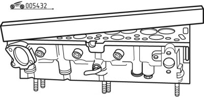
Pic. 4.32. Checking the flatness of the mating surface of the block head
1) check the flatness of the mating surface of the head with a tool, it should not be more than 0.07 mm (pic. 4.32)
Pic. 4.33. Checking the combustion chamber
2) check the protrusion into the combustion chambers using tools, the protrusion should be within (0,015±0,015) mm (pic. 4.33);
Pic. 4.34. Checking the value of drowning valves relative to the mating surface
3) check the sinking of the valve discs relative to the mating plane using tools (pic. 4.34), it must be within:
- (0,775±0,275) mm for intake valve;
- (1,175±0,275) mm for exhaust valve;
4) select the cylinder head gasket, for which perform the following operations:
- remove the crankshaft locking tool;
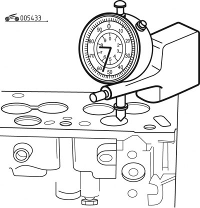
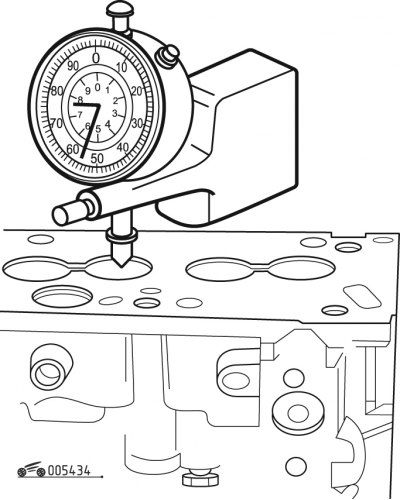
Pic. 4.35. Determining the protrusion of pistons relative to the mating surface
- install the dial indicator on the stand and adjust it on the mating surface (pic. 4.35);
- turn the crankshaft using the crankshaft turn tool;
- measure the protrusion of each piston above the mating surface of the block at top dead center;
- note the maximum protrusion;
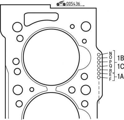
Pic. 4.36. DW8 cylinder head gasket marking (early release models): 1A - engine marking; 1B - nominal thickness; 1C - repair thickness
- select according to the table. 4.3 head gasket of appropriate thickness.
Table 4.3. Gasket selection for early release models
| Protrusion, mm | Marking |
| 0,56-0,67 | 1 hole |
| 0,68-0,71 | 2 holes |
| 0,72-0,75 | 3 holes |
| 0,76-0,79 | 4 holes |
| 0,80-0,83 | 5 holes |
Note. Marking of gaskets of models of early releases is shown in fig. 4.36. The gasket should be selected in accordance with the table. 4.3.
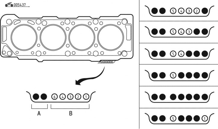
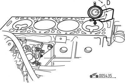
Pic. 4.37. DW8 cylinder head gasket marking (later models): A - engine marking; B - thickness marking
The marking of the gaskets of the models of the last years of production is shown in fig. 4.37. The gasket should be selected in accordance with the table. 4.4.
Identification of head gaskets for models of earlier releases is indicated in table. 4.5.
Table 4.4. Selection of gaskets for later models
| Protrusion of pistons, mm | Gasket thickness, mm | Number of holes in zone A | Number of holes in zone B |
| 0,51-0,55 | 1,26±0,04 | 2 | 1 |
| 0,55-0,59 | 1,30±0,04 | 2 | 2 |
| 0,59-0,63 | 1,34±0,04 | 2 | 3 |
| 0,63-0,67 | 1,38±0,04 | 2 | 4 |
| 0,67-0,71 | 1,42±0,04 | 2 | 5 |
| 0,71-0,79 | 1,46 0,04 | 2 | 3 |
Table 4.5. Identification of head gaskets by hole pattern
| Engine identification code | WJZ | WJZ |
| engine's type | DW8 | DW8 |
| Peculiarities | CURTY | ELRING |
| Engine marking Group (1A) | E-F | E-F |
| 1st nominal size Group (1B) | N | N |
| 2nd nominal size Group (1B) | N-O | N-O |
| 3rd nominal size Group (1B) | N-O-P | N-O-P |
| 4th nominal size Group (1B) | N-O-P-Q | N-O-P-Q |
| 5th nominal size Group (1B) | N-O-P-Q-R | N-O-P-Q-R |
| 1st repair size Group (1C) | - | - |
| 2nd repair size Group (1C) | - | - |
Install the cylinder head in the following order:
- 1) turn the crankshaft using the crankshaft turn tool;
- 2) fix the flywheel;
- 3) check the presence of the dowel pins;
- 4) install a new cylinder head gasket;
- 5) make sure the camshaft and pulley are in the valve timing position;
- 6) install the block head;
- 7) brush the threads of the cylinder head bolts;
- 8) install new washers;
- 9) apply MOLYKOTE G RAPIDE PLUS to the threads and under the bolt heads;
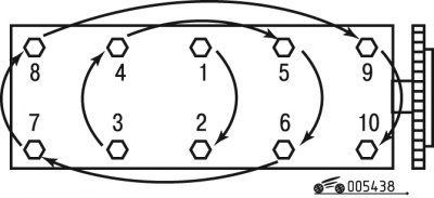
Pic. 4.38. Cylinder head bolt tightening sequence
- 10) tighten the head mounting bolts in the sequence shown in fig. 4.38, in three steps:
- pre-tightening torque 20 Nm;
- tightening torque 60 Nm;
- tighten at an angle of 180°using a tool;
- 11) install the camshaft pulley by tightening the bolts to 23 Nm;
- 12) install the timing belt;
Pic. 4.39. Installing the liquid outlet unit: 1, 2 - bolts; 3 - liquid removal unit
- 13) install block 3 (pic. 4.39) liquid drainage with a new sealing gasket, tightening the fastening bolts 2 to a torque of 14 Nm;
- 14) install a new diesel fuel filter assembly with a new O-ring, tightening bolt 1 to 18 Nm.
Continue installation in the reverse order of removal by doing the following:
- connect and secure in the clamps the wiring harnesses, fittings and cables attached to the cylinder head;
- remove air from the power system;
- fill the engine cooling system and remove air from it;
- carry out programming of all electronic devices.