



Table of contents: Engine DW10 TD 🠇 DW8 Engine 🠇
Engine DW10 TD
When removing and installing the timing belt, Peugeot service centers use the following special tool:
- belt Tension Measuring Device - SEEM C.TRONIC (type 105.5M);
- crankshaft Locking Tool - 0188-Y;
- camshaft Locking Tool - 0188-M;
- belt support device - 0188-K;
- flywheel stopper - 0188-F;
- crankshaft Turning Key - 0117-EZ;
- traverse - 0102-D;
- chain for lifting and hanging - 0102-M;
- belt tensioner lever stop - 0188-J2;
- pulley puller - 0188-P;
- set of plugs - 0188-T.
Remove the timing belt in the following order:
Caution! Remove the intake pipe to avoid damaging the flexible link (bellows), which cannot withstand torsional, tensile or bending loads that may occur when dismantling one of the powertrain suspension elements.
- remove the front right wheel;
- remove the front right mudguard;
- remove the accessory drive belt;
- remove the supply line from the turbocharger;
- remove the clutch housing guard;
- secure the flywheel with a stopper;
- loosen the auxiliary drive pulley mounting bolt;
- screw the bolt back in without the washer;
- remove the accessory drive pulley using a tool;
- remove the lower reaction control arm;
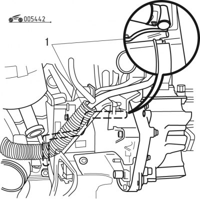
Figure 4.42. Fixing the flywheel: 1 - stopper
- turn the crankshaft with a key and lock the flywheel with a locking device 1 (figure 4.42);
- disconnect the negative battery cable;
- remove the protective cover and set it aside;
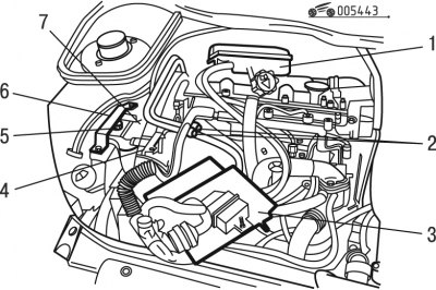
Figure 4.43. Removing parts in the underhood space: 1 - expansion tank; 2 - fuel pipes; 3 - control unit; 4 - right engine support; 5 - emphasis; 6 - jumper; 7 - timing belt cover
- remove expansion tank 1 (figure 4.43);
- remove the electronic control unit with the bracket;
- disconnect and move aside the fuel pipes 2;
Note: Close the holes in the tubes with plugs.
- remove jumper 6;
- remove stop 5;
- remove the casing 7 of the gas distribution mechanism;
- hang the engine using a crossbar by a special eye or lift it using a jack installed underneath it;
- cover the radiator cells with a sheet of thick cardboard cut to the size of the radiator;
- remove the right support 4 of the engine mount;
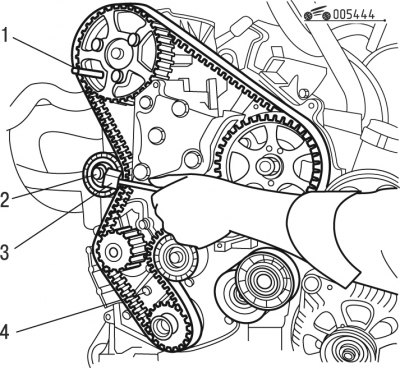
Figure 4.44. Removing the timing belt: 1 - device; 2-intern; 3 - tensioner roller; 4 - toothed belt
- secure the camshaft pulley using tool 1 (figure 4.44);
- loosen the fastening of tensioner roller 2, then tighten the fastening again in the maximum loosened position with a torque of 1 N·m;
- remove toothed belt 4.
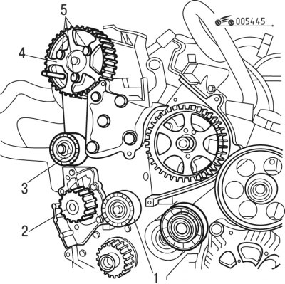
Figure 4.45. Preparing for timing belt installation: 1, 3 - rollers; 2 - water pump pulley; 4 - camshaft pulley; 5 - bolts
Install the timing belt in the following order:
Attention! Make sure that rollers 1 and 3 (figure 4.45) and pulley 2 of the water pump rotate freely, without gaps or jams. Also make sure that the rollers do not make noise and that grease splashes do not fly off them.
- unscrew bolts 5;
- make sure pulley 4 rotates freely;
- tighten the bolts 5 by hand;
- loosen bolts 5 by 1/6 turn;
- turn pulley 4 clockwise until it stops;
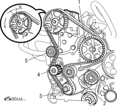
Figure 4.46. Installing the timing belt: 1 - pulley; 2, 5 - rollers; 3 - device; 4 - water pump pulley
- install the belt on the crankshaft pulley, securing the belt using tool 3 (figure 4.46) and then onto guide roller 2;
- install the timing belt on pulley 1;
- turn the camshaft pulley slightly against its working direction to fit the belt onto the gear;
Caution! The angular displacement (a) of the pulley relative to the belt must not exceed the width of one tooth.
- put the belt on the roller 5 of the tensioner 5 and on the pulley 4 of the water pump;
- move tensioner roller 5 to the belt;
- tighten the tensioner roller mounting bolt with a preliminary force of 1 N·m;
- remove device 3.
Install the belt using the device in the following order:
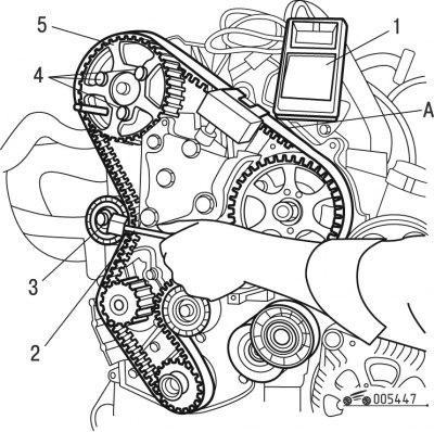
Figure 4.47. Timing belt pre-tensioning: 1 - device-adaptation; 2 - device; 3, 4 - bolts; 5 - pulley; A - belt span
- install fixture 1 (figure 4.47);
Note: Make sure that device 1 does not touch surrounding mechanisms.
- turn the tensioner roller counterclockwise using tool 2;
- achieve belt tension of (106±2) SEEM units;
- tighten bolt 3 to 2.3 Nm (without changing the position of the roller);
- remove fixture 1;
Attention! When unscrewing bolt 4 of pulley 5, make sure that these bolts do not rest against the loop. Otherwise, start installing the timing belt again.
- tighten bolts 4 until they stop in the pulleys;
- tighten bolts 4 to 20 Nm;
- remove the clamps 1 (see figure 4.42 and 4.44);
- turn the crankshaft 8 revolutions in the direction of working rotation.
Caution! Never turn the crankshaft in the opposite direction.
Perform the final tensioning of the timing belt in the following order:
- install clamps 1 (see figure 4.42 and 4.44);
- loosen the tightening torque of bolts 4 (see figure 4.47);
- tighten the bolts 4 by hand;
- loosen bolts 4 by 1/6 turn;
- loosen the tightening torque of bolt 3;
- install device 1 on belt span A;
- turn the tensioner roller counterclockwise using tool 2;
- achieve belt tension of (54±2) SEEM units;
- tighten bolt 3 to 23 Nm without changing the position of the roller;
- tighten bolts 4 to 20 Nm;
- remove tool 1 to relieve internal stress;
- re-install the device 1. The belt tension value should be 51-57 conventional units of SEEM;
Note: If the obtained belt tension value is outside the specified values, loosen the belt and proceed to re-tension it.
- remove the device-fixture 1;
- remove the clamps 1 (see figure 4.42 and 4.44).
Check the correct adjustment of the gas distribution mechanism in the following order:
- turn the crankshaft 2 revolutions in the direction of working rotation and do not turn it in the opposite direction;
- reinstall the retainer 1 (see figure 4.42);
Caution! Visually check that the distance between the hole in the camshaft flange and the hole for the corresponding retainer is no more than 1 mm.
- remove the lock 1.
Complete the timing belt installation in the following order:
- install the lower timing case;
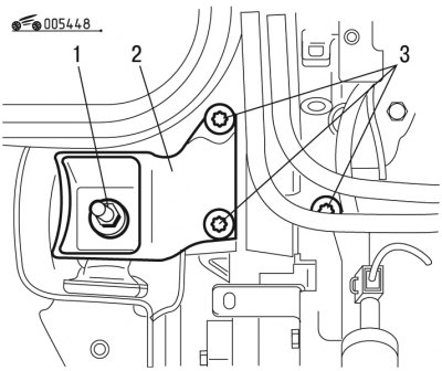
Figure 4.48. Installing the engine support: 1 - nut; 2 - support; 3 - bolts
- install support cushion 2 (figure 4.48) engine;
- tighten three bolts 3 with a torque of 45 Nm;
- tighten nut 1 to 45 Nm;
- install casing 7 (see figure 4.43) gas distribution mechanism;
- install stop 5, tightening the fastening parts to a torque of 32 Nm;
- install jumper 6, tightening the fastening parts to a torque of 21.5 N·m;
- secure the flywheel with a stopper;
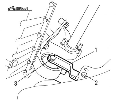
Figure 4.49. Installing the reaction lever: 1 - lever; 2, 3 - bolts
- install the reaction lever 1 (figure 4.49) engine mounts;
- tighten bolt 3 to 50 Nm;
- tighten bolt 2 to 35 Nm;
- install the accessory drive pulley;
- use a M163150 tap to tap the internal thread of the crankshaft for the pulley mounting bolt;
- clean the threads on the bolt with a brush;
- tighten the bolt to 40 Nm, after applying LOCTITE FRENETANCH sealant;
- tighten the bolt to an angle of 50° using a device such as FACOM D360);
- check the tightening torque to 195 Nm;
- install the accessory drive belt;
- remove the flywheel retainer;
- install the shield, tightening the fastening parts to a torque of 18 N·m;
(Source of the article is website: PEUGEOTBOOK.ru)
Caution! The exhaust system clamp must be replaced with a new one regularly.
- install exhaust system components;
- tighten the wheel bolts to a torque of 85 Nm.
Complete subsequent installation in the reverse order of removal, then program all electronic devices.
DW8 Engine
When removing and installing the timing belt, Peugeot service centers use the following special tool:
- belt tension measuring device — SEEM C.TRONIC 105.5M;
- crankshaft locking tool - 0188-D;
- camshaft Locking Tool with Bolt M83803125 - 0188-E;
- high pressure pump adjustment device - 0188-H;
- belt support device - 0188-K;
- flywheel stopper - 0188-F;
- crankshaft turning key - 0117-EZ.
- traverse - 0102-D;
- hanging hooks - 0102-J;
- auxiliary tension lever - 0188-J1.
Remove the timing belt in the following order:
- disconnect the negative battery cable;
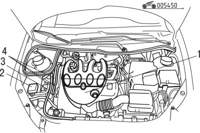
Figure 4.50. Removing parts in the underhood space: 1 - protective cover; 2 - electronic unit; 3, 4 - tubes
- remove protective cover 1 (figure 4.50);
- disconnect fuel pipes 4 and 3;
- disconnect the electronic unit 2;
- remove the front right wheel;
- remove the front right mudguard;
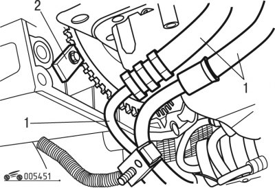
Figure 4.51. Removing the power steering pipes: 1 - tubes; 2 - device
- disconnect and move aside tubes 1 (figure 4.51) power steering, passing in the engine area;
- remove the protective board;
- install fixture 2;
- loosen the tensioner roller fastening;
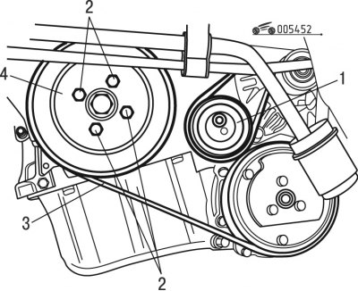
Figure 4.52. Removing the accessory drive belt: 1 - tension roller; 2 - bolts; 3 - belt; 4 - pulley
- remove the accessory drive belt by removing the tension roller 1 (figure 4.52), unscrew bolts 2 and remove pulley 4 of the crankshaft;
- cover the radiator cells with a sheet of thick cardboard cut to the size of the radiator;
- install the crossbar with chains and, hooking them onto the engine eye, tighten;
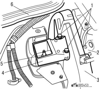
Figure 4.53. Removing the engine mount: 1 - bolts; 2 - eye; 3 - timing belt cover; 4 - support; 5 - nut; 6 - gasket
- move aside gasket 6 (figure 4.53);
- unscrew nut 5;
- unscrew three bolts 1;
- remove engine support cushion 4;
- remove the casing parts 3 of the gas distribution mechanism;
- remove the lower timing case;
- remove fixture 2 (see figure 4.51);
- turn the crankshaft with a wrench;
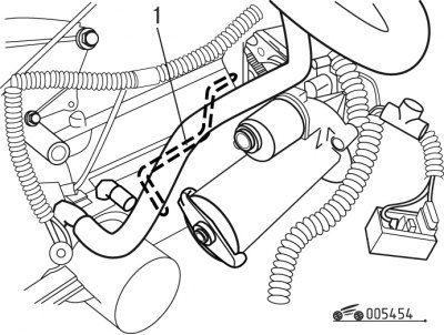
Figure 4.54. Fixing the flywheel: 1 - device
- secure the engine flywheel using tool 1 (figure 4.54), without removing the starter;
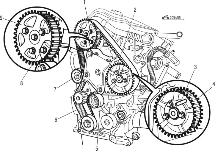
Figure 4.55. Fixing the camshaft pulley: 1, 2 - bolts; 3, 8 - clamps; 4, 9 - pulleys; 5 - roller; 6 - belt; 7 - tensioner roller
- secure the camshaft pulley using tool 8 (figure 4.55);
- adjust the high pressure fuel pump (HPFP) using tool 3;
- loosen the tensioner roller 7;
- re-tighten the fastener to its maximum loose position;
- remove toothed belt 6.
Install the timing belt in the following order:
Note: Make sure rollers 5 and 7 rotate freely (without play or jamming). Also make sure that the rollers do not make noise and do not spray grease.
- unscrew bolts 1 and 2 (see figure 4.55);
- make sure pulleys 4 and 9 rotate freely on their hub;
- tighten bolts 1 and 2 by hand, then back off 1/6 turn;
- turn two pulleys 4 and 9 clockwise until they stop in the loop;
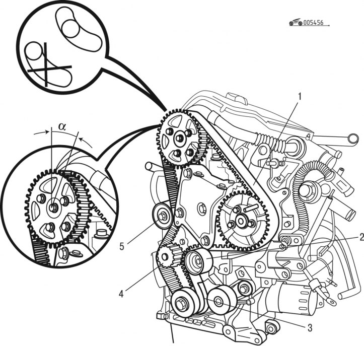
Figure 4.56. Installing the timing belt: 1 - belt; 2 - roller; 3 - device; 4 - water pump pulley; 5 - tensioner roller
- install the belt on the crankshaft pulley, securing the belt using tool 3 (figure 4.56);
- install guide roller 2;
- install timing belt 1 on pulley;
- turn the camshaft pulley slightly against the direction of the working movement to fit the belt onto the pulley;
Caution! The angular displacement (a) of the pulley relative to the belt must not exceed the width of one tooth.
- put the timing belt on the tensioner roller 5 and on the water pump pulley 4;
- move tensioner roller 5 to the belt;
- tighten the tensioner roller mounting bolt to a preliminary torque of 1 N·m;
- remove device 3.
Pre-tension the timing belt in the following order:
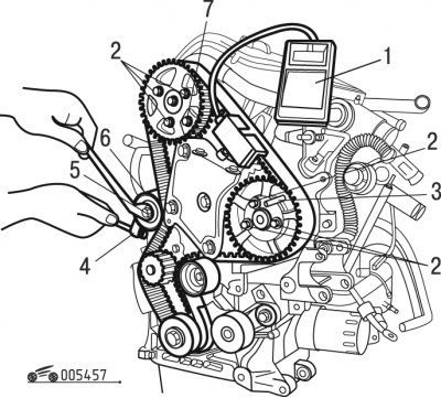
Figure 4.57. Timing belt tension: 1 - device; 2 - bolts; 3, 7 - clamps; 4 - device; 5 - nut; 6 - tensioner roller
- install device 1 on the belt (figure 4.57);
Note: Make sure that the device does not touch surrounding mechanisms.
- turn tensioner roller 6 counterclockwise using tool 4;
- achieve tension of (106±2) SEEM units;
- tighten nut 5 to 18 Nm without changing the position of roller 6;
- remove device 1;
Attention! When unscrewing bolts 2 securing pulleys 4 and 9 (see figure 4.55) make sure the bolts 2 (see figure 4.57) do not rest against the loop. Otherwise, proceed to reinstall the timing belt.
- screw bolts 2 into the pulleys until they stop;
- tighten bolts 2 to 23 Nm;
- remove retainer 1 (see figure 4.54) and clamps 3 and 8 (see figure 4.55);
- turn the crankshaft 8 revolutions in the direction of working rotation (clockwise);
Caution! Never turn the crankshaft in the opposite direction.
Perform the final tensioning of the timing belt in the following order:
- install clamp 1 (see figure 4.54) and clamps 3 and 8 (see figure 4.55);
- loosen the tightening torque of bolts 2 (see figure 4.57);
- loosen the tightening torque of nut 5;
- tighten bolts 2 by hand, then loosen by 1/6 turn;
- install device 1 on span A of the belt;
- turn tensioner roller 6 counterclockwise using tool 4;
- achieve belt tension of (41±2) SEEM units;
- tighten nut 5 to 18 Nm without changing the position of roller 6;
- tighten bolts 2 to 23 Nm;
- remove device 1;
- reinstall the device 1;
Note: The tension value should be equal to 38-42 SEEM units.
Caution: If the obtained belt tension value is outside the specified values, loosen the belt tension and proceed to re-tension.
- remove device 1 (see figure 4.57), retainer 1 (see figure 4.54) and clamps 3 and 8 (see figure 4.55).
Check the correct adjustment of the gas distribution mechanism in the following order:
- turn the crankshaft 2 revolutions in the direction of working rotation and do not turn it in the opposite direction;
- reinstall the retainer 1 (see figure 4.54);
- check visually and make sure that the deviations between the holes of the camshaft and fuel injection pump hubs and the holes for their alignment are no more than 1 mm;
- remove retainer 1.
Complete the installation of the timing components in the following order:
- install the lower timing case;
- install support cushion 4 (see figure 4.53) engine;
- install the timing case parts;
- tighten nut 5 (see figure 4.53) torque of 45 Nm;
- tighten three bolts 1 to 45 Nm;
- secure the flywheel with tool 2 (see figure 4.51);
- install pulley 2 (see fig 4.52) crankshaft;
- tighten bolts 4 to 10 Nm;
- install tension roller 1;
- install the accessory drive belt as described above;
- install the shield, tightening its fastening parts to a torque of 19 Nm;
- install the remaining units and mechanisms in the reverse order of removal.