



Table of contents: XUD9 engines 🠇 2.1 liter engine 🠇
The following work is performed after complete and partial removal of the timing belt.
When removing the engine mount, the power unit must be secured to a beam or hoist.
XUD9 engines
1. Loosen the right front wheel mounting nuts.
2. Jack up the right front side of the car and place a stand under the body.
3. Remove the right wheel.
4. Disconnect the negative (-) battery terminal.
5. Remove the mudguards and sound insulation from the wheel arch.
6. Engage the gear and remove the belt pulley bolt on the crankshaft.
Source available on the website (peugeotbook)
7. Remove the belt pulley. To do this, use two pry bars or a puller.
8. Attach a rope or chain to the engine lifting eye and lift the engine with a hoist or similar device. You can also place a garage lift under the engine, place some wooden blocks on it, and carefully lift the engine to take the weight off the mounts.
9. Remove the timing belt guard. In this case, move the upper part first forward and then upward. Then release the second, lower, part of the casing from the pins and remove it as well. Remove the spacer sleeve (see illustration).
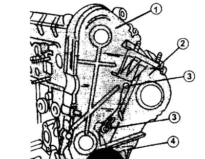
24.9 Fastening the toothed belt protective cover
1 - upper part of the protective casing
2 - lower part of the protective casing
3 - protective cover mounting pins
4 - spacer sleeve
10. Prepare two MX x 1.25 bolts, 40 mm long. Insert one bolt into the camshaft gear at point 1, and the other into the high-pressure fuel pump drive gear at point 2 (see illustration).
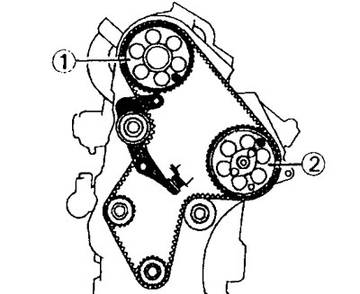
24.10 Procedure for blocking the gas distribution mechanism. The black dots mark the holes into which the pins are inserted
1 - camshaft gear
2 - fuel injection pump drive gear
This way the valve timing mechanism is blocked. The general appearance of the gas distribution mechanism is shown in Illustration 24.10a.
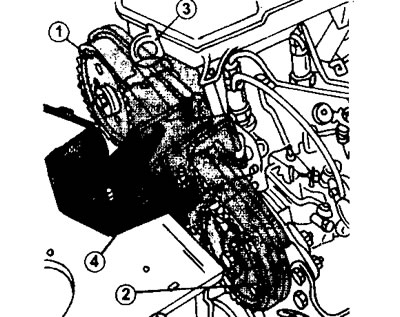
24.10a Timing mechanism parts
1 - timing belt gear on the camshaft
2 - fuel injection pump drive gear
3 - eye for removing the engine
4 - engine support bracket
11. Loosen bolt 1 and nut 2 of the timing belt tensioner (see illustration).
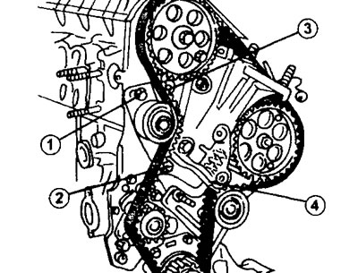
24.11 Timing belt tensioner. 1.9 liter engine
1 - bolt
2 - nut
3 - hole for a square key
4 - pressure spring
Insert a 9.52 mm (3/8 in) square wrench into hole 6 of the tensioner (extended ratchet handle) (see illustrations 17.16 and 17.17). Turn the key to compress the tensioner spring.
12. Tighten bolt 2 to secure the timing belt tensioner in the new position (see illustration).
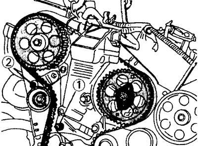
24.12 The automatic toothed belt tensioner is held in place by nut 1 and bolt 2
13. Remove the timing belt from the camshaft gear, and then from the remaining gears. If this timing belt is to be reinstalled, mark its direction of rotation with a marker. If a new belt is installed, the timing belt tensioner and tension roller must also be replaced (see illustration).
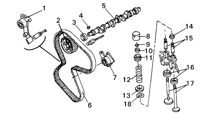
24.13 Details of the XUD9 engine timing mechanism
1 - timing belt tensioner
2 - camshaft timing belt gear
3 - camshaft oil seal
4 - key
5 - camshaft
6 - toothed belt
7 - timing belt tension roller
8 - plate pusher
9 - valve clearance adjusting washer
10 - valve cracker
11 - valve spring plate
12 - valve spring
13 - valve spring support washer
14 - oil seal
15 - valve guide sleeve
16 - valve seat ring
17 - valves
18 - spacer washer
All other parts are replaced with new ones depending on the need.
14. Make sure that there is no oil or grease on the parts that come into contact with the timing belt. The thrust bolts should be in the holes of the camshaft and fuel injection pump gears. If these bolts were removed during the work, the camshaft must be rotated to allow the M8 bolt to be inserted into hole 7 (see illustration).
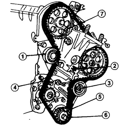
24.14 Installing a timing belt on a 1.9 liter engine.
1 - tension roller
2 - Timing belt tensioner spring pusher
3 - guide roller
4 - toothed belt
5 - timing gear of the toothed belt on the crankshaft
6 - gear mounting bolt
7 - thrust bolt in the camshaft gear hole
In this position the gears can be fitted with a toothed belt.
15. Loosen bolt 1 and nut 2 (see illustration 24.11) the timing belt tensioner so that the tension roller moves back to its original position. Make sure the tension roller is set to the correct position and tighten bolt 1 and nut 2.
16. Insert the thrust bolt into the corresponding hole on the fuel injection pump gear. This position of the fuel injection pump corresponds to the moment of fuel injection into cylinder chamber #1.
17. Lock the crankshaft in the TDC position by inserting the thrust rod into the hole on the flywheel as shown in illustrations 17.77.
18. Install the timing belt. It is first placed on the crankshaft gear, then on the guide roller and on the fuel injection pump gear, and after that on the camshaft gear. Keeping the timing belt tensioned, secure it to the water pump gear and tension roller.
19. Make sure the belt teeth are properly seated on the gears.
20. Screw in the timing belt sprocket mounting bolt onto the crankshaft, placing a lining washer on it, and tighten the bolt.
21. Loosen bolt 1 and nut 2 (see illustration 24.11), to release the tensioner roller.
22. Remove all the bolts that were used to secure the shafts, as well as the flywheel locking rod.
23. Turn the crankshaft at least two revolutions in the direction of engine rotation to align the position of the timing belt.
Loosen bolt 1 and nut 2 of the timing belt tensioner again (see illustration 24.11). In this case, the tension roller is set to the belt tensioning position. After this, tighten the bolt and nut to a torque of 18 Nm.
24. Turn the engine over a few revolutions and reinsert the timing drive lock bolts. If the bolts are difficult to insert, this means that the valve timing adjustment is out of adjustment and the entire work must be done again.
25. Remove the bolt and washer that secures the timing belt gear to the crankshaft.
26. Install the three parts of the timing belt guard.
27. Install the belt pulley on the crankshaft and screw in the bolt with the washer. Lubricate the bolt threads with Loctite. While holding the crankshaft steady, tighten the belt pulley mounting bolt to 40 Nm. From this position, tighten the bolt an additional 60°.
All other work is carried out in the reverse order of removal.
28. Tighten bolt 1 and nut 2 of the timing belt tensioner (see illustration) with a torque of 20 Nm.
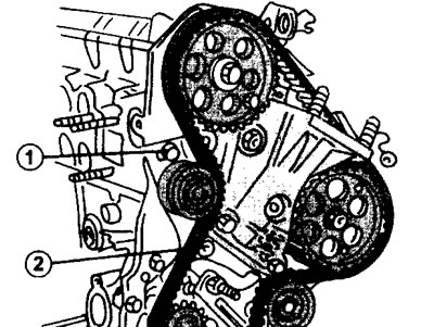
24.28 Tighten bolt 1 and nut 2 of the timing belt tensioner (see illustration) with a torque of 20 Nm
29. Install the engine mount, flywheel and clutch guard.
2.1 liter engine
To remove the timing belt on this type of engine, it is necessary to perform all work, including removing the protective cover of the timing belt, in the same sequence as indicated for the 1.9 liter engine (see illustration 24.0a).

24.0a Remove the timing belt guard, consisting of three parts (1-3), by unscrewing the mounting bolts marked with arrows. 2.1 liter engine
30. Attach a rope or chain to the engine and lift the engine with a hoist or similar device. You can also place a garage lift under the engine, place some wooden blocks on it, and carefully lift the engine to take the weight off the mounts.
31. Remove the right engine mount.
32. Prepare two M8x1.25 bolts, 40 mm long. Insert one bolt into the camshaft gear at point 1, and the other into the high-pressure fuel pump drive gear at point 2 (see illustration).
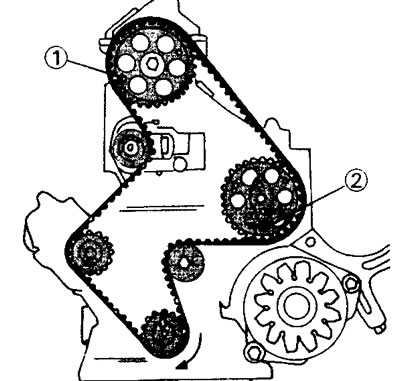
24.32 Secure gear 1 of the camshaft and gear 2 of the fuel injection pump drive with stop bolts to prevent them from turning
This way the valve timing mechanism is blocked.
33. Remove the protective cover from the flywheel and clutch, and lock the flywheel accordingly or engage the gear.
34. Loosen the bolt securing the belt pulley to the crankshaft and remove the pulley using two pry bars or a puller.
35. Loosen the timing belt tension. To do this, unscrew nut 1 of the tension roller, as well as bolt 2, using a 5 mm socket wrench (see illustration).
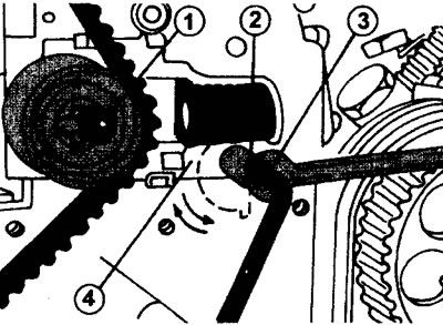
24.35 Removing and installing the timing belt on a 2.1 liter engine.
1 - tension roller nut
2 - tensioner bolt
3 - 5 mm socket wrench
4 - tensioner eccentric
36. Use a 10 mm socket wrench and turn the eccentric 4 with it (see illustration 24.35) to the right to loosen the belt tension and remove it. If this timing belt is to be reinstalled, mark its direction of rotation with a marker. If a new belt is installed, the timing belt tensioner and tension roller must also be replaced. All other parts are replaced with new ones depending on the need.
37. Make sure that there is no oil or grease on the parts that come into contact with the timing belt.
If the timing belt gear was removed from the crankshaft, it must be installed in place. Be careful not to displace the key that secures the gear.
The thrust bolts should be in the holes of the camshaft and fuel injection pump gears. If these bolts were removed during the work, the camshaft must be rotated to allow the M8 bolts to be inserted into holes 1 and 2 (see illustration 24.32).
38. Install the timing belt. If you are installing the same belt, follow the belt rotation direction mark. It is first placed on the fuel injection pump gear, then on the guide roller, on the crankshaft and water pump gears, and then on the camshaft gear and tension roller.
39. Make sure the belt teeth are properly seated on the gears.
40. Remove all the bolts that were used to secure the shafts, as well as the flywheel locking rod.
41. Loosen nut 1 (see illustration 24.35), so that the tensioner roller moves towards the belt and tightens it.
42. Turn the crankshaft at least two revolutions in the direction of engine rotation to align the position of the timing belt. In this case, the tension roller is set to the belt tensioning position. After this, tighten nut 1 of the tension roller with a torque of 10 Nm (see illustration 24.35).
43. Crank the engine several times and re-insert the timing drive lock bolts. If the bolts are difficult to insert, this means that the valve timing adjustment is out of adjustment and the entire work must be done again.
44. Install the three parts of the timing belt guard.
45. Install the belt pulley on the crankshaft and screw in the bolt with the washer. Lubricate the bolt threads with Loctite. While holding the crankshaft steady, tighten the belt pulley mounting bolt to 40 Nm. From this position, tighten the bolt an additional 60°.
All other work is carried out in the reverse order of removal. Don't forget to reinstall the flywheel and clutch disc guards.