
It should not be forgotten that before disassembling the engine, all removed parts must be marked accordingly, so that they can then be installed properly if they are to be reinstalled. This applies in particular to pistons, valves, bearing caps and bearing shells. When removing these parts, stack them in such a way that they are not mixed up.
Do not mark or write on bearing cap or sealing surfaces with a scriber or sharp object. To do this, there is paint or a felt-tip pen. The valves can be installed in a cardboard box by punching holes in the bottom of the box and marking each valve with the appropriate number (see illustration 3.0).
Many parts are made of aluminum and must be handled properly. If a hammer is needed to separate them, then use rubber, plastic or leather.
Mount the motor on a suitable mounting stand. In the absence of such a stand, install the engine on a workbench, securing it from the sides from tipping over. In this case, maximum care must be taken not to damage the intake manifold.
In the absence of a workbench, you can use wooden blocks, sawn and laid in such a way that access is provided to both the lower and upper parts of the engine installed on them.
The removed cylinder head is clamped in a vise together with a plate that is attached to the intake manifold studs.
1.9 liter engine disassembly
If the engine is being dismantled for the purpose of a complete overhaul, then a number of appropriate tools must be available. In addition to the set of keys necessary for such work (regular and overhead), interchangeable socket heads, we recommend preparing an oil filter wrench, piston ring pliers, a mandrel for installing pistons, a micrometer for measuring, a puller with two or three jaws, a torque wrench, a steel ruler, an inside gauge for measuring the inner diameter of the cylinder bore, as well as an indicator for measuring the axial movement of the crankshaft.
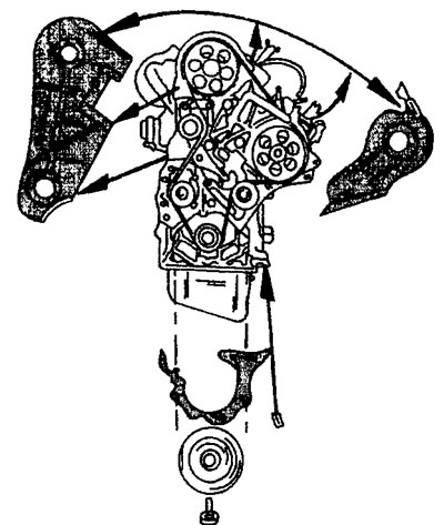
1. Disconnect the engine mount by removing the four mounting bolts.
2. Disconnect the turbocharger oil outlet pipe.
3. Disconnect the oil filter attached to the side of the engine using the filter wrench (see illustration).
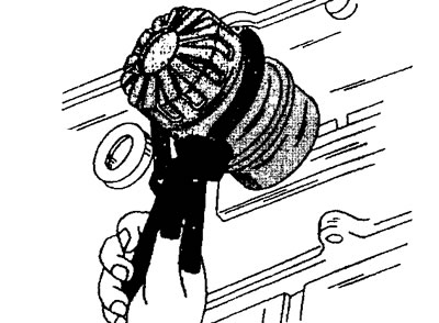
17.3 Disconnect the oil filter attached to the side of the engine using the filter wrench
4. Remove the rod pointer (probe) engine oil level.
5. Turn out bolts of fastening and remove pressure and conducted disks of coupling. To prevent the flywheel from turning at the same time, secure it with a brake shoe by installing it on the ring gear (see illustration).
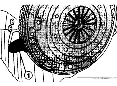
17.5 Locking the flywheel against rotation when removing the clutch pressure and driven plate using the brake shoe 1
If this shoe is not available, secure the flywheel with a screwdriver. Unscrew six bolts of fastening of disks of coupling in a cross order.
6. Remove driven disc from flywheel. At the same time, do not touch the driven disk with oily fingers.
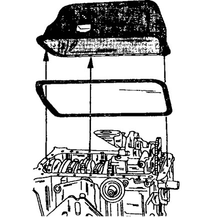
7. Remove, if installed, the heater radiator, the fuel filter with the base, the oil intake with the hoses connected to it, the thermostat housing cover and remove the thermostat (see illustration).
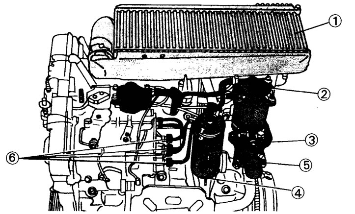
17.7 Remove the parts adjacent to the injection pump
1 - heater radiator
2 - fuel filter
3 - coolant outlet pipe
4 - oil intake
5 - thermostat housing cover
6 - union nuts for fastening high-pressure fuel lines
8. Disconnect the coolant outlet pipe, unscrew the union nuts of the high pressure fuel lines and disconnect the fuel lines (see illustration 17.7). Cover the fuel line openings to prevent dirt from getting in.
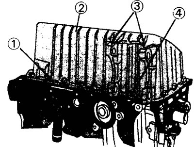
9. Turn away bolts of fastening and remove the generator fixed on this side of the engine, the power steering pump (if available), a cover for mounting units, a cable to increase idle speed.
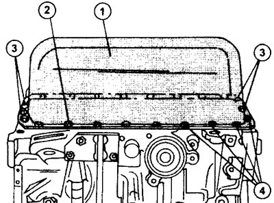
10. Remove the exhaust manifold, vacuum pump, intake manifold inlet pipe, air intake sleeve and coolant inlet (see illustration).
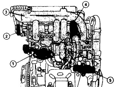
17.10 Parts removed from the engine from the side of the exhaust manifold.
1 - exhaust manifold
2 - vacuum pump
3 - intake manifold intake pipe
4 - air intake sleeve
5 - coolant inlet pipe
11. Remove the oil pan. To do this, turn the engine so that the crankcase is on top and unscrew the 23 mounting bolts, loosening them evenly (see illustration).
17.11 Removing the oil pump
Mark the mounting position of the pan mounting bolts and fold them separately.
12. Remove the oil pan gasket.
Attention! The above procedure for removing the oil pan applies to engines with a sheet iron pan. Engines in air-conditioned vehicles have aluminum oil pans. In this case, the pallet attachment is slightly different from the above. And although in this case it is necessary to unscrew the 23 fastening bolts, however, only 20 bolts are the same in length. Two have a different size and one is completely different from all (see illustration 17.0).
17.0 Aluminum oil pan mounting (cars with air conditioning).
1 - 20 bolts 22 mm long
2 - oil pan
3 - 2 bolts 40 mm long
4 - 1 bolt 20 mm long
13. Turn out, keeping the flywheel from turning (see illustration 17.5).
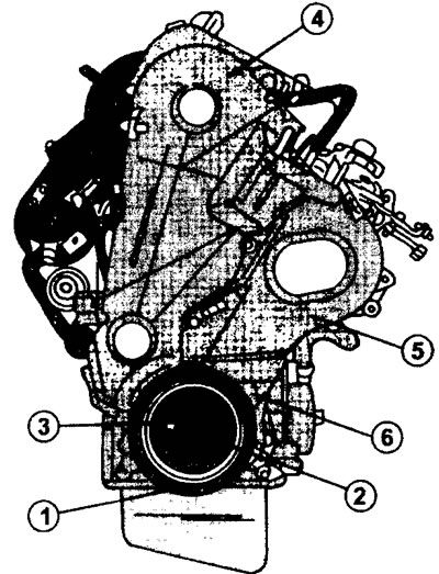
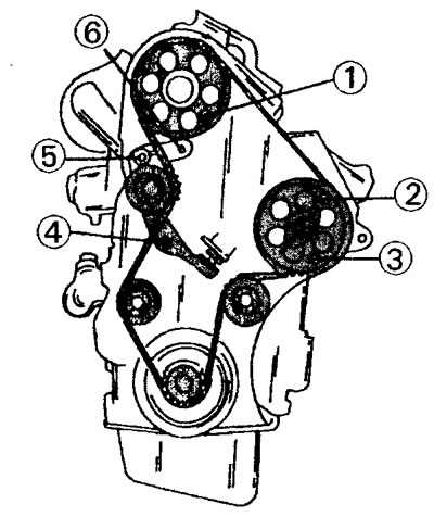
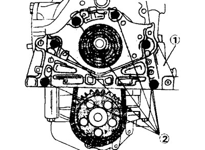
17.15 Front of the engine assembly.
1 - belt pulley
2 - a bolt of fastening of a belt pulley
3 - gear
4 - upper part of the toothed belt guard
5 - side part of the toothed belt guard
6 - bottom protective panel
belt pulley bolt on the crankshaft. After that turn out bolts of fastening of a flywheel and disconnect it. Tap the flywheel with a plastic hammer if necessary. The mounting position of the flywheel does not need to be marked, because it can only be installed in one position.
14. Remove the belt pulley from the crankshaft using two pry bars. If possible, you can use a puller by screwing its bolts into the holes on the pulley.
15. Remove both parts of a protective casing of a gear belt. Open the protective cover fastening clamp with a screwdriver. Remove the bottom cover as well (see illustrations 17.15 and 17.15a).
17.15a The front of the engine. The arrows show the parts to be dismantled
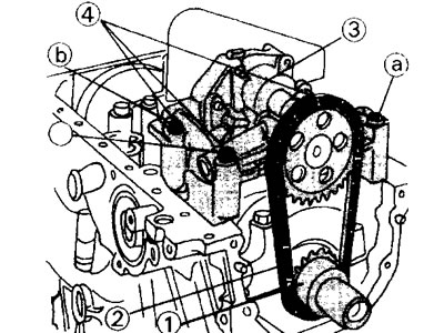
16. Prepare three M8x1.25 bolts 40 mm long. Insert one of them into hole 1 on the camshaft gear, and the remaining two into holes 2 and 3 of the injection pump drive gear (see illustration).
17.16 Fixing the gas distribution mechanism.
1 - hole 1 for installing the bolt M8x1.25
2 - hole 2 for installing the M8x1.25 bolt
3 - hole 3 for installing the bolt M8x1.25
4 - belt tensioner bolt
5 - belt tensioner nut
6 - hole for a square
This ensures the fixation of the gas distribution mechanism. However, if the engine needs to be completely disassembled, then the above work is unnecessary. Bolts are inserted only in cases where it is necessary to avoid shifting the timing adjustment.
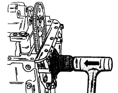
17. Unscrew the nut 4 and loosen the bolt 5 of the toothed belt tensioner (see illustration 17.16). Install a square wrench (size 9.52 mm) into hole 6 under the square to compress the spring of the automatic toothed belt tensioner (see illustration 17.17).
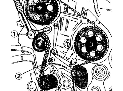
17.17 Unscrew nut 2 and loosen the toothed belt tensioner bolt (it is closed with a ratchet 1). Install a ratchet wrench 1 with a square in the hole for the square to compress the spring of the automatic toothed belt tensioner
A 3/8" square is included with the end bits. Bolt 5 tighten again to fix the tensioner in its new position (see illustration 17.16).
18. Remove the toothed belt, being careful, from both gears.
19. Turn away bolts of fastening of a head of the block of cylinders and remove a head (see relevant chapter).
20. Remove the timing belt timing gear from the crankshaft. If necessary, use two mounts.
21. Remove bolts 2 and 3 and remove tensioner 4 (see illustration).
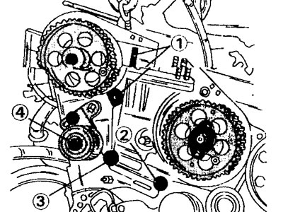
17.21 Remove tensioner 4 by unscrewing bolts 1, 2 and 3
In workshops, a special tool is used to hold the tensioner spring and pusher.
22. Turn out two bolts 1 and remove the tension roller 2 of a gear belt located on the center (see illustration).
17.22 Turn out two bolts of fastening and remove the roller of a tension of a gear belt located on the center.
1 - mounting bolts
2 - tension roller
3 - water pump
This will allow you to unscrew the mounting bolts and remove the water pump 3.
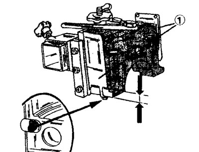
23. Remove the side cover (bearing shield), installed in front of the oil pump. The seal is pressed into the cover. In order to remove the cover, you need to unscrew the six mounting bolts (see illustration).
17.23 Remove side cover 1 (bearing shield), installed in front of the oil pump. To remove the cover, unscrew six bolts 2
The mounting position of the bolts must be noted because they differ in length. The cover itself is mounted on centering pins and therefore it should be removed with sufficient care.
24. Turn out three bolts of fastening of the oil pump on the underside of the engine. If there is a spacer, remove it by pushing it to the side in the direction of the arrow (see illustration).
17.24 Turn out three bolts of fastening of the oil pump (see arrow). If there is a spacer, remove it by pushing it to the side in the direction of the arrow
25. Remove the drive chain from the oil pump sprocket (see illustration).
17.25 Oil pump before disassembly
1 - oil pump drive sprocket on the crankshaft
2 - drive chain
3 - oil pump mounting bolts
4 - oil pump
5 - driven sprocket of the oil pump
26. Remove the oil pump drive sprocket from the crankshaft, remove the key and remove the chain.
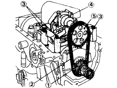
27. Remove the toothed belt gear from the camshaft, as well as the injection pump drive gear.
28. Remove high pressure fuel pump and disconnect fuel lines. In order to remove the injection pump, it is necessary to disconnect the support on the back of the injection pump, and then unscrew the three mounting bolts.
29. Turn away nuts of fastening of rod bearings and remove covers. Pull out the pistons along with the connecting rods and stow them properly. Make sure the markings on the caps and connecting rods are clearly visible. Otherwise, additionally mark them with paint (see illustration).
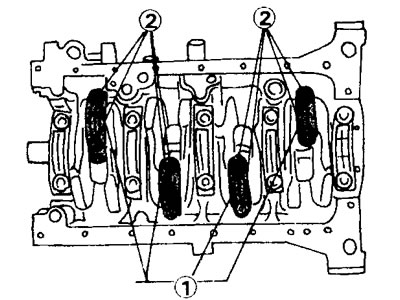
17.29 Loosen the connecting rod bearing nuts 1 and remove the caps by unscrewing eight nuts 2
30. Designate covers of radical bearings by numbers from 1 to 5 (cover #1 should be located near the flywheel) and take them off. Place the main bearing shells and caps together.
31. Remove the crankshaft oil seal from the flywheel side. The seal must be replaced with a new one.
32. Remove the crankshaft and upper halves of the bearing shells.
33. Mark and remove the thrust semi-rings for adjusting the axial runout of the crankshaft.
Dismantling of pistons and connecting rods is carried out in the order given in the corresponding chapter.
1.9 liter engine assembly
The procedure for assembling petrol engines applies in general to diesel engines (see relevant chapter).
34. Assemble the pistons and connecting rods in accordance with the instructions in the relevant chapter.
35. Install the connecting rod bearing shells in accordance with the marking (see illustration),
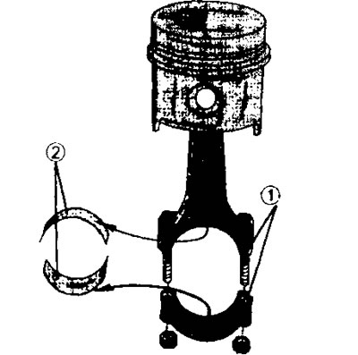
17.35 Piston assembly with connecting rod. On the connecting rod and on the bearing cap there are corresponding marks 1, 2 - liners, installed as shown by arrows. There is an arrow on the bottom of the piston, which should also be guided during assembly
if they are not replaced, but reinstalled. The guide tabs on the bushings must fit into the holes in the connecting rods.
36. Insert the main bearing shells with lubrication grooves in the crankcase bed. The guide lugs of the bushings must fit into the corresponding recesses.
37. Install oil jets at the bottom of the cylinder block, if the engine is equipped with one.
38. Install on each side of bearing No. 2 (counting is carried out from the side of the flywheel) both half rings for adjusting the axial play of the crankshaft. The lubrication grooves on both half rings must face outwards, towards the sliding surface of the crankshaft. Lubricate the thrust half rings well with engine oil.
39. Install, being careful, the crankshaft in the bearings. The surfaces of the necks must be well lubricated with engine oil. To do this, use an oil can and rub the oil with your finger. Do not use a brush for this.
40. Install bearing caps Nos. 2, 3, 4, and 5 with inserted bushings in the order in which they were before removal. Bearing cap No. 2 should have thrust half rings. The bearing caps are numbered and the cap numbers must face the oil filter. Do not install bearing cap on flywheel side yet (see illustration).
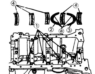
17.40 Engine crankcase. Make sure the thrust washers are properly installed.
1 - oil nozzles
2 - thrust semi-ring for adjusting the axial movement of the crankshaft, mounted on bearing No. 2
3 - thrust semi-ring for adjusting the axial movement of the crankshaft, mounted on bearing No. 2
4 - main bearing shells with grooves
41. Check up axial movement of a cranked shaft.
42. Install a dial indicator with a suitable holder on the end of the engine, so that the measuring rod touches the end of the crankshaft (see illustration).
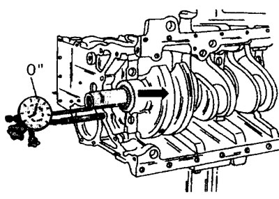
17.42 Checking the axial movement of the crankshaft
If the holder is magnetic, then the indicator can be mounted on the shaft, and the measuring rod must rest against the polished surface of the cylinder block.
43. Press the crankshaft towards the flywheel with a screwdriver and set the indicator needle to «0».
44. Press the crankshaft from the flywheel to the toothed belt. The value of axial displacement recorded by the indicator should be within 0.07-0.32 mm. If the result obtained exceeds 0.32 mm, then it is necessary to install the stop half rings of the repair size (increased thickness). In this case, it is necessary to install both half rings of the same thickness so that the crankshaft does not move. In addition to half rings with a nominal thickness of 2.30 mm, there are half rings with a thickness of 2.35, 2.40, 2.45 and 2.50 mm.
To install the rear bearing cover, you need a special tool for mounting the side seals of the cover.
45. Apply sealing compound to the surface of the crankcase in contact with the bearing cover (see arrows in illustration).
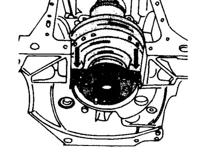
17.45 Apply sealing compound to the surface of the crankcase in contact with the bearing cover
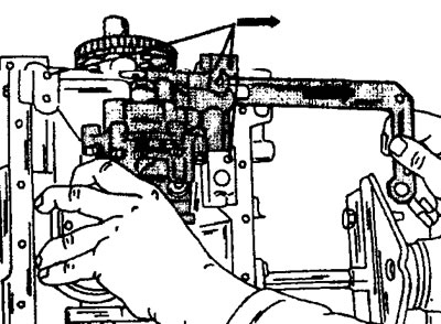
46. Screw both guide rails 1 to the fixture. Do not tighten the bolts tightly (see illustration).
17.46 Screw both guide rails 1 to the fixture. The guides press the side seals into the grooves. At the bottom, the seals should protrude as shown in the illustration
47. Fix the two rubber seals on both sides of the rear bearing cover with a toolholder. The seals are precisely matched in length and do not need to be trimmed. Fasten the holder with one bolt to the bearing cap and lubricate the guides with engine oil.
48. Squeeze the guide bars with your hand and insert them all together at a slight angle into the cylinder block until the cover is seated in place. To do this, after entering the device into the block, you need to press on the device.
49. Install both bearing cap bolts and hand tighten.
50. Disconnect the adaptation from a cover and take it together with directing levels from the block of cylinders.
51. Tighten the bolts of all bearing caps in order, working from the middle outward, with a torque of 70 Nm.
52. Return the two bolts to the crankshaft flange and insert a screwdriver between them. You can use bolts to mount the flywheel. Rotate the crankshaft to check its travel and make sure it is not stuck anywhere. And only after this check, the assembly of the engine can be continued.
53. Lubricate the outer side of the new oil seal and press it into the hole on the cylinder block from the flywheel side. The gland can also be driven in by placing a metal plate on it. But in this case, the plate must fit snugly against the surface of the stuffing box. Drive the gland in carefully so as not to damage it.
54. Arrange the assembled pistons and connecting rods in order of installation. Fix a mandrel on the piston of the first cylinder to install it in the cylinder and insert it into the cylinder bore well lubricated with engine oil, guided by the appropriate marking (see illustration).
17.54 Installation of pistons. Attach a mandrel to the piston to install it in the cylinder and insert it into the cylinder bore well lubricated with engine oil
In this case, drive the connecting rod so that it sits on the connecting rod neck. When reinstalling the old connecting rod bearings, do not mix them up. After installing the piston and connecting rod, make sure that the combustion chamber cavity in the piston is located correctly. This means that the arrow on the piston pin must point in the direction on which the toothed belt is located. Install the piston of the fourth cylinder in the same way.
55. Insert loose leaves of bearings of both established rods, observing their marking. Lubricate the bearing surfaces well with engine oil. Bearing nuts must be replaced with new ones. Pre-tighten the bearing cap with a torque of 20 Nm and then tighten it by 70°using a goniometer.
56. Turn the crankshaft so that the necks of the two remaining pistons are in the lower position. Install the remaining two pistons with connecting rods. After installing them, check the free play of the crankshaft and make sure that it does not wedge anywhere.
Before installing the oil pump, put the chain on the driven sprocket, and then fix the oil pump. If a spacer is installed, then insert it from the side of the oil filter between the pump and the cylinder block, i.e. in reverse order to what is shown in illustrations 17.24. Oil pump bolts vary in length (see illustration).
17.56 The oil pump bolts are of different lengths.
1 - drive sprocket on the crankshaft
2 - drive chain
3 - oil pump
4 - oil pump mounting bolts: a - bolt 80 mm long b - bolt 70 mm long c - bolt 65 mm long
Their tightening torque is 18 Nm.
57. Install and secure the side cover (bearing shield), by updating the gasket. The cover is attached with six bolts of different lengths (see illustration 17.23). Two bolts for fastening the top of the cover are 35 mm long, the rest are 18 mm long. Tighten all bolts with a torque of 12 Nm.
58. Press the oil seal flush with a suitable mandrel into the bearing shield, sliding the oil seal onto the crankshaft. The mandrel must be in contact with the entire surface of the stuffing box (see illustration).
17.58 Using a suitable mandrel, press the oil seal into the bearing shield flush with the oil seal on the crankshaft. The mandrel must be in contact with the entire surface of the stuffing box
59. Install a new oil pan gasket to the crankcase. If the engine has a sheet iron sump, then secure it with 23 bolts by screwing them in in accordance with the marks made when removing the sump. Tighten the bolts evenly with a torque of 16 Nm (see illustration).
17.59 Fixing the oil pan made of sheet iron.
1 - oil pan
2 - bolt 20 mm long
3 - bolts 16 mm long
4 - bolts 20 mm long
The aluminum oil pan is mounted on the crankcase with a dowel pin. In this case, a gasket is not needed, however, the mating surfaces are lubricated with a sealing mass. The pallet mounting bolts are screwed in in accordance with the marks applied before removal and tightened with a torque of 16 Nm (see illustration 17.0).
60. Attach the flywheel to the crankshaft. To do this, rotate the flywheel until the mounting holes are aligned. The flywheel mounting bolts must be replaced with new ones. Lubricate the threads of the bolts with protective paste. Before tightening the mounting bolts, the flywheel must be secured against turning (see illustration 17.5). Tighten the flywheel mounting bolts evenly with a force of 50 Nm.
61. Install the clutch pressure and driven discs on the flywheel. The extended side of the driven disc hub must face outwards. Install the pressure plate only after aligning the marks made by the core before removal (if old clutch parts are installed). Holding the flywheel from turning, tighten the mounting bolts in a crosswise manner with a torque of 14 Nm (see illustration).
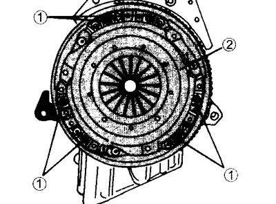
17.61 Fastening pressure and driven clutch discs.
1 - mounting bolts
2 - clutch pressure plate
Make sure that the centering rod enters freely and is removed from the hole into which the input shaft of the gearbox will subsequently be wound.
62. Install the high pressure fuel pump. Do not tighten the pump mounting nuts, as well as its rear support yet.
Cylinder head gaskets are available in different thicknesses. The thickness of the cylinder head gasket to be installed depends on the height of the piston protrusion above the surface of the cylinder block. In order to determine how thick a gasket is needed, the pistons must be sequentially set to the TDC position and the protrusion of each piston above the surface of the cylinder block must be measured. The cylinder head gaskets are notched on the outside. Due to the fact that since the release of this engine, changes have been made to the marking of gaskets, it is not possible to indicate the only correct designation of the desired gasket. In addition, changes were constantly made to the designation of gaskets.
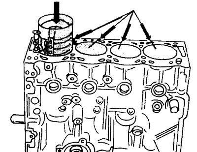
63. Install a dial indicator on a magnetic holder on a well-cleaned surface of the cylinder block and press the measuring pin against the surface of the block near the outside of the piston. In this position «zero out» indicator (see illustration).
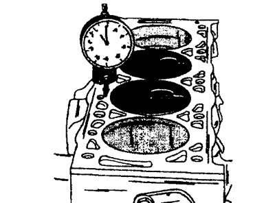
17.63 Measurement of the height of the protrusion of the pistons of the cylinders
64. Move the measuring pin as close as possible to the middle of the piston, without removing the instrument itself from the surface of the cylinder block. Read the resulting value and write it down (see illustration).
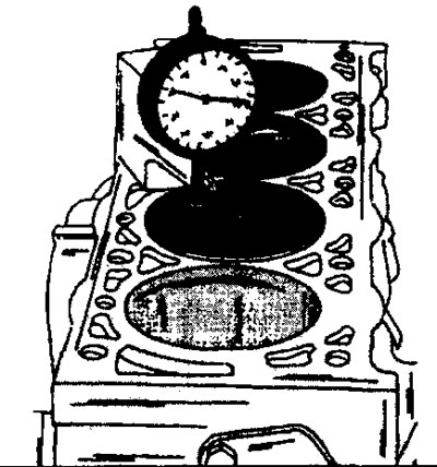
17.64 Move the measuring pin as close as possible to the middle of the piston without removing the instrument itself from the surface of the cylinder block
It corresponds to the height of the piston protrusion.
Measure the protrusion of the remaining pistons in an identical way, and also write down the obtained values. The maximum protrusion value is decisive when selecting the cylinder head gasket. However, the difference between the values obtained during measurements on any two pistons should not exceed 0.12 mm.
The gasket is selected as follows. If the protrusion of the pistons is within 0.54-0.77 mm, then a gasket should be installed that has three notches at point A, and two at point B (see illustration 17.0a). The thickness of such a gasket is 1.54 mm.
If the protrusion of the pistons is in the range of 0.77-0.82 mm, then a gasket should be installed that has three notches both at point A and at point B (see illustration 17.64a).
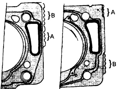
17.64a Options for cylinder head gaskets. At point A, the type of engine is indicated, and at point B, the thickness. Notches A and B can be located either side by side or at a certain distance from each other
The thickness of such a gasket is 1.64 mm.
After determining the height of the protrusion of the pistons, rotate the crankshaft so that all pistons are approximately in the center of the cylinder bores. Only then can further assembly of the engine be continued.
65. Make sure that the centering pin 1 is installed on the cylinder block (see illustration)
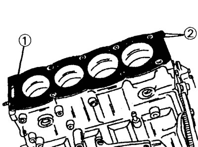
17.65 Install the centering pin 1 to install the cylinder head. The notches on the head gasket must face 2
and install the cylinder head (see relevant chapter). Adjust valve clearance (see relevant chapter).
66. Install the water pump, replacing the old gasket with a new one. Tighten the water pump mounting bolts to 15 Nm.
67. Screw both thermal switches into the holes on the thermostat housing.
68. Install two new gaskets on the thermostat and install it in the housing. Secure the fully assembled thermostat housing to the cylinder block with a new gasket.
69. Remove the gear from the camshaft, installed to adjust the valve clearance, and stuff the camshaft oil seals, slightly lubricating their working surface with engine oil.
70. Install the camshaft gear. Tighten the gear mounting bolt with a torque of 45 Nm. When tightening the bolt, hold the camshaft from turning. To do this, you can insert the rod into the hole on the gear and fix it in the cylinder head.
71. Tighten the injection pump mounting bolts.
72. Turn the crankshaft, camshaft and injection pump shaft so that the keys on these shafts are in position as shown in (illustrations 17.72).
17.72 The arrows show the position of the keys on the shafts
73. Install the drive gear on the injection pump shaft and secure it with a bolt by screwing it into the hole in the center of the gear. Tighten the bolt with a torque of 50 Nm, keeping the gear from turning.
74. Install the timing gear on the crankshaft and, without moving the key, drive it onto the shaft using a piece of pipe.
75. Insert into hole 1 on the camshaft gear one of the M8x40 mm bolts used when disassembling the engine (see illustration 17.16). The bolt in this case enters the hole on the cylinder head, thereby fixing the gear from turning when laying the toothed belt.
76. Fix the injection pump drive gear in the same way. Bolts are installed in holes 2 and 3 (see illustration 17.16).
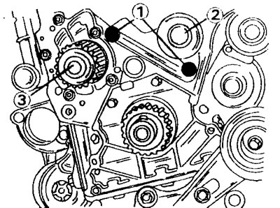
77. Secure the crankshaft from turning. To do this, you need a metal rod 8 mm thick. The rod is inserted from the rear side of the cylinder block and goes into the hole on the flywheel, locking it in position (see illustration).
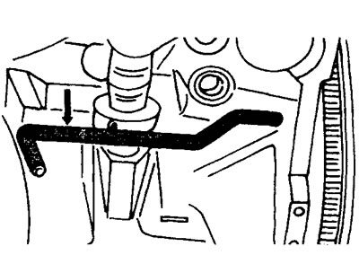
17.77 Lock the crankshaft from turning with a rod that is inserted from the rear of the cylinder block and fits into the hole on the flywheel, locking it in position
78. Lay the timing belt. First, put the belt on the crankshaft gear, then lead through the guide roller in the center to the injection pump drive gear, camshaft gear, to the tension roller and finally to the water pump gear. Make sure that the teeth of the belt are tightly engaged with the teeth of all gears.
79. Tighten the toothed belt (see relevant chapter).
80. Adjust the injection timing of the injection pump (see relevant chapter).
81. Install the belt pulley on the crankshaft. Lubricate the thread of the pulley mounting bolt with protective grease «Loctite», screw in the bolt and tighten it with a torque of 40 Nm, and then tighten it by 60°. At the same time, hold the crankshaft from turning by fixing the flywheel.
82. Screw in the glow plugs and tighten them to 22 Nm. Fasten the current-carrying bar on the four contact pins of the candles and fix with nuts, tightening them with a torque of 4 Nm.
83. Screw nozzles (tightening torque 90 Nm) and connect the high pressure fuel lines to them by screwing the union nuts with a torque of 20 Nm.
84. Install the toothed belt guards. Tighten the latch at the junction of the casings with a screwdriver.
85. Install the oil filter and tighten it to 14 Nm. Before doing this, lubricate the filter rubber ring well with engine oil.
The remaining parts are installed in the reverse order of disassembly. The tightening torque of the exhaust manifold nuts is 20 Nm, the intake manifold is 23 Nm.