



If the adjustment is performed without removing the engine from the car, then it is necessary to remove the cylinder head cover to gain access to the valves.
1. Place the front of the vehicle on jack stands and engage high gear. In this position, you can turn the engine to adjust the valve clearance.
2. Draw a sign as shown in (illustrations 21.2),
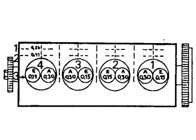
21.2 Table for recording when adjusting valve clearances.
Line 1 = valve clearance obtained by measurement
Line 2 = difference after subtracting nominal value from measured value
Line 3 = nominal value
in order to then enter the values obtained during the check to adjust the gap.
[Source of the article is posted at: PeugeotBook.ru]
3. Turn the engine in the direction of travel using a freely hanging wheel. To measure valve clearance, the cam lobe of the corresponding valve must be facing upwards. This means that the opposite valve of this cylinder is in the "Open" position. Cylinder #1 is located near the flywheel. The valve clearance is measured using a suitable template inserted between the cam lobe and the valve lifter.
4. Enter the obtained value in column I of the table. In this case, the obtained value is 0.26 mm (see illustration 21.2).
Turning the engine half a turn in the direction of travel each time, measure the clearance of all valves and record the obtained values. The nominal valve clearance for intake valves is 0.15 mm, and for exhaust valves, it's 0.30 mm. If the resulting value doesn't match the nominal value, the clearance must be adjusted by installing adjusting shims of a different size between the valve lifters and the valve stem. If the gap is greater than the nominal value, thicker adjusting washers are installed. When reduced in size - thinner (see illustration 21.4).
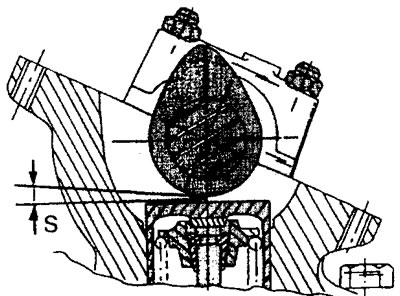
21.4 Measure the gap S using a suitable template
5. Remove the valve lifter and the adjusting washer located underneath it (see illustration).
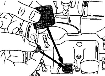
21.5 Remove the valve tappet 2 and the adjusting washer 1 located underneath it
Clean the adjusting washer and measure its thickness.
6. Determine the thickness of the new washer. The procedure is as follows: the nominal value must be subtracted from the valve clearance obtained by measuring (see illustration).
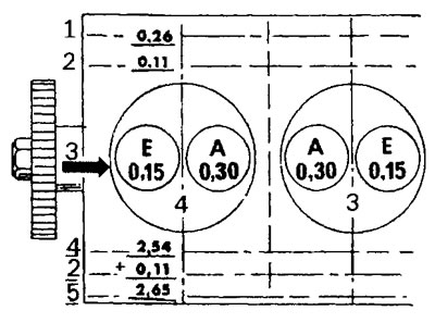
21.6 Calculating the thickness of a new washer to adjust the valve clearance. The letter E denotes the intake valves, and the letter X denotes the exhaust valves
Line 1 = valve clearance obtained by measurement
Line 2 = difference after subtracting nominal value from measured value
Line 3 = nominal value
The clearance adjustment value can be either positive or negative. If the value is positive, a thicker adjusting washer must be installed. If the value is negative, a thinner washer is installed. The average value of the permissible range of values is taken as the nominal value. The thickness of the new adjusting washer is determined as the sum of the obtained measurement value and the adjustment value.
7. Select a new adjusting washer whose thickness best matches the value obtained during addition. Adjusting washers are available in thicknesses ranging from 2.425 to 3.550 mm. The thickness increment is 0.075 mm. Before measuring and installing, remove any grease from the washers.
Caution: When replacing the camshaft or tappets, always install a 2.425 mm thick washer (nominal value) regardless of the thickness of the washers that were there before replacement.
8. Lubricate the valve lifters and install them in place. Once installed, the tappets must not be lifted. This may cause the adjusting washer to change its position. Therefore, if the installed pusher needs to be raised, it must be removed completely, the adjusting washer must be reinstalled, and then the pusher must be inserted.
9. Install the camshaft and perform all work related to installing the timing belt.
10. Turn the camshaft at least two revolutions. Rotate the shaft very slowly. At the same time, check the valve clearance again using a measuring template. Make the necessary adjustments if necessary (see illustration).
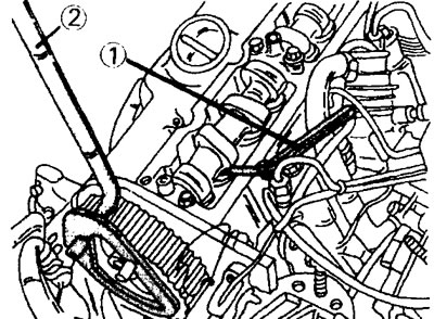
21.10 Checking the valve clearance using a measuring template 1. For this purpose, the camshaft can be rotated using a rotating device 2
11 Install all remaining parts in the reverse order of disassembly.