
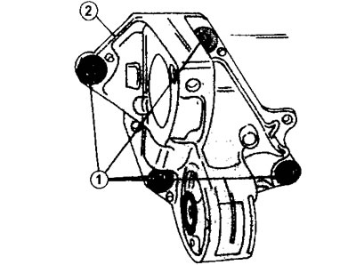
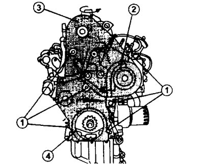
18.1 Disconnect the engine support 2 by unscrewing the four mounting bolts 1
2. Disconnect the turbocharger oil outlet pipe.
3. Disconnect the oil filter attached to the side of the engine using the filter wrench (see illustration 17.3). Unscrew the connecting sleeve 3 and remove the oil cooler 2, as well as the oil pressure regulator 1 (see illustration).
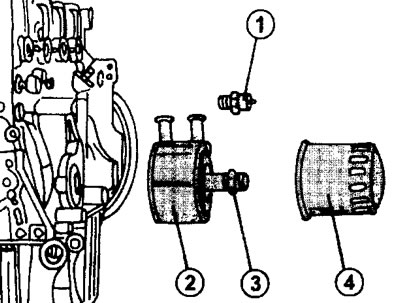
18.3 Unscrew the connecting sleeve 3 and remove the oil cooler 2, as well as the oil pressure regulator 1, 4 - oil filter
The tightening torque for the coupling sleeve is 58 Nm.
4. Remove the rod pointer (probe) engine oil level.
5. Disconnect the box 2 of the air intake, fixed to the engine, made of plastic. To do this, unscrew five bolts 1, including three that secure the upper part, and two bolts that secure the lower part (see illustration).
18.5 Disconnect the air intake box 2 fixed to the engine by unscrewing five bolts 1
Remove the box.
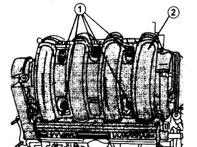
6. Disconnect and remove the intake manifold. Before doing this, remove the clamps at the bottom and top of the connecting pipe of the exhaust gas recirculation system and disconnect the pipe. After that, unscrew the 6 nuts securing the intake manifold. Remove the manifold gasket (see illustration).
18.6 Remove the clamps at the bottom and top of the connecting pipe of the exhaust gas recirculation system and disconnect the pipe.
1 and 3 clamp clamps
2 - branch pipe of the exhaust gas recirculation system
7. Turn out bolts of fastening and remove pressure and conducted disks of coupling. To prevent the flywheel from turning at the same time, secure it with a brake shoe by installing it on the ring gear (see illustration 17.5). If this shoe is not available, secure the flywheel with a screwdriver. Given that the flywheel is fixed with a shoe, it is possible to unscrew the bolt securing the belt pulley to the crankshaft. After that, remove the belt pulley from the crankshaft using a three-jaw puller, if necessary.
8. Remove the toothed belt guard (see illustration).
18.8 Remove the toothed belt guard. To release the shroud, turn the top mount a quarter of a turn
1 - casing mounting bolts
2 - side cover
3 - top cover
4 - bottom cover
To release the shroud, turn the top fastener a quarter of a turn.
9. Turn out four bolts of fastening of an arm of the right support of a suspension bracket of the engine and disconnect an arm. The following work concerns the removal of the toothed belt. The crankshaft, camshaft and drive gear of the injection pump must be secured against rotation so as not to disturb the setting of the gas distribution mechanism.
10. Turn the crankshaft until the holes on the camshaft gear and high pressure fuel pump match the holes on the engine designed to install the thrust bolts (see illustration).
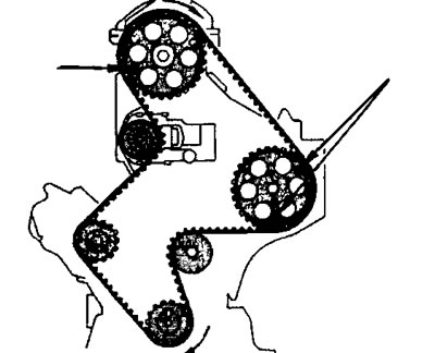
18.10 Turn the crankshaft until the holes on the camshaft gear and high pressure fuel pump coincide with the holes on the engine intended for installing thrust bolts
This operation is omitted if the engine is completely overhauled.
The crankshaft is also secured against turning (see illustration 17.77). If the engine is disassembled, then the need to fix the crankshaft also disappears.
11. Unscrew the nut 1 of the tension roller 2, the nut 3 and the bolt 4. To unscrew the bolt 4, a 5 mm socket wrench is needed, and to hold the adjusting eccentric 5 of the tensioner, a 10 mm wrench (see illustration).
18.11 Unscrew the nut 1 of the tension roller 2, the nut 3 and the bolt 4. To unscrew the bolt 4, a 5 mm socket wrench is needed, and to hold the adjusting eccentric 5 of the tensioner, a 10 mm wrench
12. Turn the eccentric to the right to loosen the toothed belt, and press the tension roller outward and tighten the nut 1 in this position of the roller (see illustration 18.11). On a dismantled engine, this operation is not particularly difficult. If the toothed belt is removed without removing the engine from the engine compartment, then access to the nut 1 is possible only through the corresponding hole on the engine support bracket.
13. Mark the direction of rotation of the toothed belt with a marker, if it will then be re-installed. After that, remove the belt from the corresponding gears, proceeding in order.
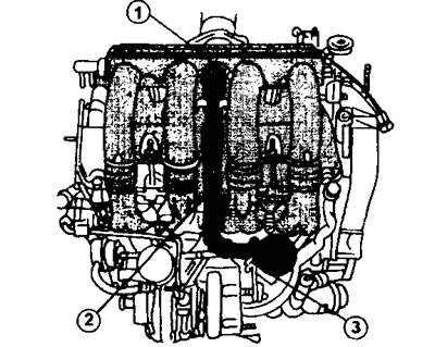
14. Disconnect all hoses and pipelines from the engine.
15. Disconnect from TNVD an accelerator cable, and also fuel lines of a high pressure. The fuel lines are fastened together in pairs with an appropriate bracket (see illustration).
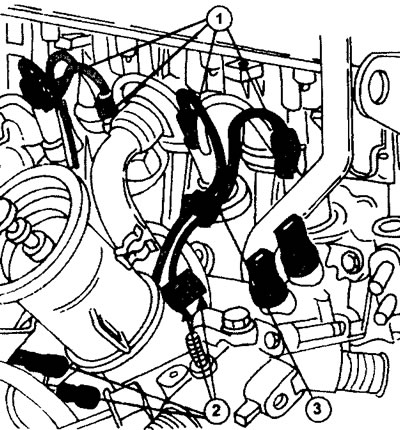
18.15 Disconnect the high-pressure fuel lines by unscrewing the cap nuts 1 and 2. The fuel lines are fastened together in pairs with an appropriate bracket
16. Turn out 11 bolts and remove a head of the block of cylinders (see relevant chapter).
17. Turn out 6 bolts of fastening of a turbocharger and remove it together with a sealing lining. The gasket must be replaced with a new one.
18. Turn out 5 bolts of fastening of the water pump and remove the pump.
19. Remove the toothed belt tension roller.
20. Remove the timing gear from the crankshaft using two pry bars or an appropriate puller.
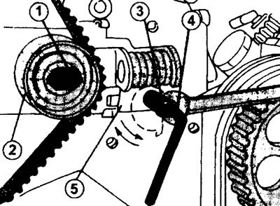
21. Lock the camshaft gear appropriately against rotation and remove the gear. In a similar way, the injection pump drive gear is removed (see illustration).
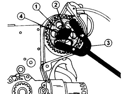
18.21 Stop the injection pump gear from turning and, having unscrewed the fastening bolts, remove it.
1 - high pressure fuel pump gear
2 - gear nut
3 - stop to keep the gear from turning
4 - gear puller
22. Remove THVD, having previously unscrewed 3 bolts of fastening of an arm.
23. Turn out, acting in a cross order, 8 bolts of fastening of a flywheel and remove a flywheel. Be careful not to let the flywheel fall.
24. Turn the engine over with the crankcase upside down and remove the oil sump. On a car engine without air conditioning, to remove the oil sump, unscrew 19 bolts on the outside of the crankcase and four socket head bolts in the corner. If available, unscrew the oil level indicator sensor fixed with two bolts.
Attention! When the engine is turned over, residual oil may leak out.
If the car is equipped with air conditioning, then to remove the oil pan, you need to unscrew 20 bolts, loosening them evenly. In addition, it is necessary to unscrew one bolt of the pallet, located on the side, as well as two bolts of the suspension of the air conditioning compressor (see illustration 17.0). The oil pan gasket is missing. At the same time, also unscrew the oil level indicator sensor. It also mounts without a gasket. Mark the mounting position of the oil pan bolts and fold the bolts separately.
25. Remove the side cover (bearing shield), installed in front of the oil pump. The seal is pressed into the cover. In order to remove the cover, you need to unscrew the six mounting bolts (see illustration 17.23). Remove the shield seal as well. The cover itself is mounted on centering pins and therefore it should be removed with sufficient care.
26. Turn out three bolts of fastening of the oil pump. Remove the drive chain from the oil pump sprocket (see illustration 17.25).
27. Remove the oil pump drive sprocket from the crankshaft, remove the key and remove the chain (see illustration 17.25).
Further disassembly of the engine is identical to the disassembly of the 1.9 liter engine (see relevant chapter).