
Disassemble the engine in the following order:
1. Turn away nuts of fastening of a cover of a head of the block of cylinders and remove a cover with a lining.
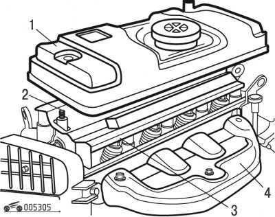
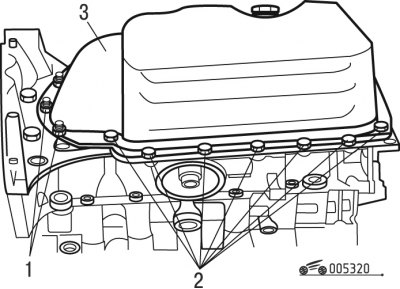
Pic. 3.5. Removing the cylinder head cover: 1 - cylinder head cover with gasket; 2 - remote bushings; 3 - oil deflector screen; 4 - exhaust manifold heat shield
2. Remove spacers 2 (pic. 3.5) and oil screen.
3. Remove the exhaust manifold heat shield.
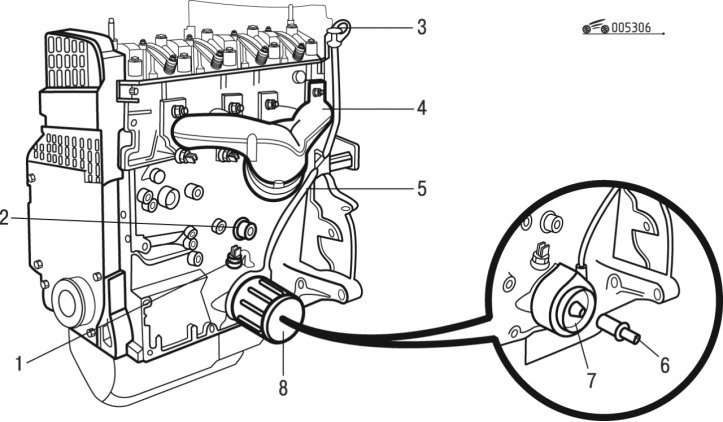
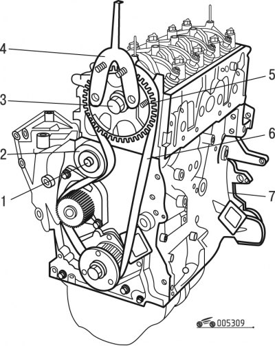
Pic. 3.6. Removing the exhaust manifold and elements located on the installation side of the exhaust manifold: 1 - oil pressure indicator sensor (depending on configuration); 2 - oil pressure warning lamp sensor; 3 - oil dipstick; 4 - exhaust manifold; 5 - probe guide tube; 6 - threaded fitting (depending on configuration); 7 - heat exchanger (depending on configuration); 8 - oil filter
4. Remove exhaust manifold 4 (pic. 3.6) and its lining.
5. Unscrew the oil filter 8.
Note. On a number of engines (depending on configuration) a heat exchanger can be installed under the oil filter, into which a threaded extension is screwed to install the oil filter.
6. Remove the threaded fitting and heat exchanger, if fitted (see fig. 3.6).
7. Remove the oil dipstick from the guide tube.
8. Remove the dipstick guide tube.
9. Using a wrench, turn out the oil pressure gauge sensor, if installed (depending on configuration) (see fig. 3.6).
10. Using a key, turn out the oil pressure warning lamp sensor.
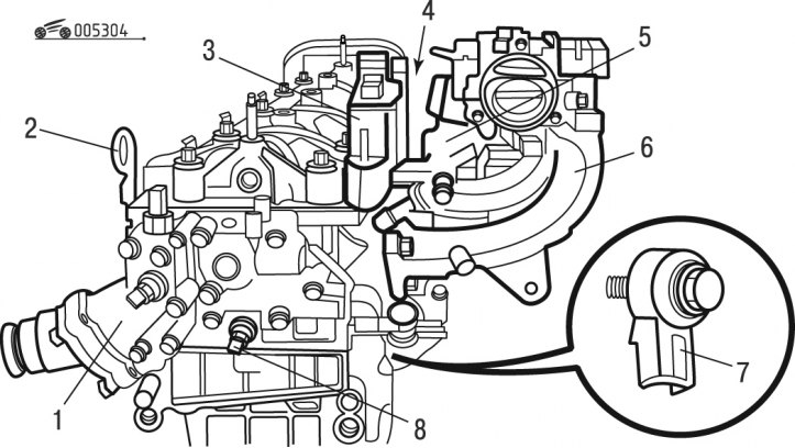
Pic. 3.7. Removing the intake manifold and elements located on the installation side of the intake manifold: 1 - thermostat block of the cooling system; 2 - eyes for slinging the power unit; 3 - block of compact ignition coils (depending on engine type); 4 - fuel rail with nozzles; 5 - intake manifold; 6 - knock sensor; 7 - coolant temperature sensor
11. From the installation side of the intake manifold, remove block 3 (depending on engine type) (pic. 3.7) ignition coils.
12. Remove the fuel rail with injectors.
13. Remove the intake manifold.
14. Remove from an end face of a head of the block of cylinders the block of the thermostat of system of cooling.
15. Turn out from an end face of a head of the block of cylinders the gauge of temperature of a cooling liquid.
16. Remove from the cylinder head the eyelets for slinging the power unit.
17. Remove the knock sensor (it is located on the cylinder block under the intake manifold).
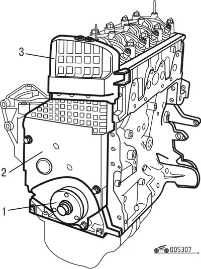
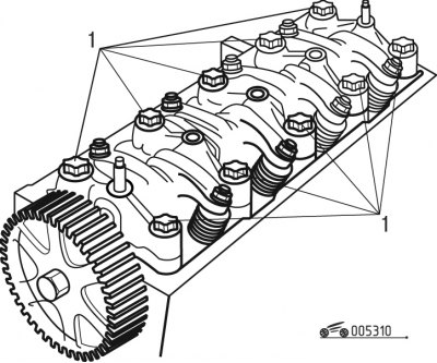
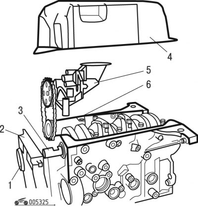
Pic. 3.8. Removing the camshaft timing belt covers: 1 - top cover of the camshaft drive belt; 2 - middle cover of the camshaft drive belt; 3 - lower cover of the camshaft drive belt
18. Remove the three camshaft timing belt covers (pic. 3.8).
Pic. 3.9. Fixing the flywheel and camshaft: 1 - a bolt of fastening of the mechanism of a tension of a toothed belt; 2 - roller of the toothed belt tensioner; 3 - a bolt of fastening of a gear pulley of a camshaft; 4 - special key; 5 - fixture 0132 A for fixing the camshaft; 6 - toothed belt; 7 - fixture for fixing the engine flywheel (depending on engine type)
19. Block the crankshaft flywheel with tool 7 (pic. 3.9) to fix it (a pin or bolt with a diameter of 6 mm can be used as a retainer), by inserting it into the hole in the front left flange of the cylinder block.
20. Turn away bolts of fastening of a pulley of a drive of the generator and remove a pulley.
21. Turn away a bolt of fastening of the mechanism of a tension of a gear belt.
22. Loosen and remove the toothed belt.
23. Remove the toothed belt tensioner pulley.
24. Block the camshaft pulley with tool 0132A, unscrew its fastening bolt and remove the pulley.
25. Remove the toothed pulley from the crankshaft.
26. Turn away bolts of fastening of the pump of a cooling liquid. Take out from a nest in the block of cylinders the pump of a cooling liquid with a lining.
Note. If complete disassembly of the engine is not required, then you can remove the cylinder head assembly with pipelines and auxiliary units.
Pic. 3.10. Loosening the cylinder head bolts: 1 - bolts of fastening of a head of the block of cylinders
Pic. 3.11. Removing the cylinder head using levers (tool 0153-Q): 1 - a set of tools for removing the cylinder head
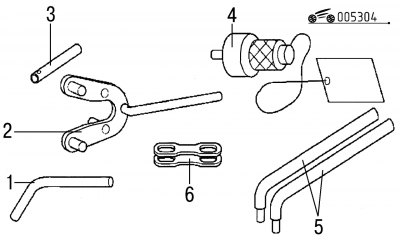
Pic. 3.4. Special tools and fixtures for engine disassembly: 1 - a device for fixing the engine flywheel; 2 - special key; 3 - a device for fixing the camshaft; 4 - flywheel stopper; 5 - levers; 6 - clamping plates for holding cylinder liners (used when dismantling engines with an aluminum cylinder block)
27. Turn away bolts 1 (pic. 3.10) fastening of a head of the block of cylinders and remove it in gathering with a camshaft. Disassemble the cylinder head if necessary. Use tool kit 0153-Q to separate the head from the cylinder block; these devices are L-shaped levers (pic. 3.11), which are inserted into the holes of the head bolts (see fig. 3.4).
Note. It is necessary to unscrew the bolts of the cylinder head, starting from the periphery in a spiral, moving to the center of the head.
28. Remove the cylinder head gasket.
Warning! Operation p. 29 - only for engines with an aluminum alloy cylinder block.
Pic. 3.12. Installation on the cylinder block of clamping plates for holding cylinder liners (tool 0132-A1Z): 1 - set of clamping plates for holding cylinder liners (tool 0132-A1Z); A - aluminum alloy cylinder block
29. Install two clamping plates 1 on the cylinder block (pic. 3.12) for holding cylinder liners. The plates are mounted on bolts that are screwed into the holes for the block head bolts.
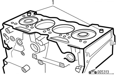
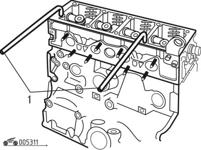
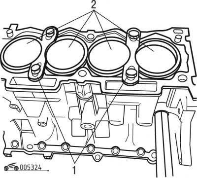
Pic. 3.13. Removing bushings to center the head on the cylinder block: 1 - bushings for centering the head on the cylinder block
30. Remove bushings 1 (pic. 3.13) for centering the head on the cylinder block.
31. Remove tool 0132-QZ (see fig. 3.4) to fix the engine flywheel.
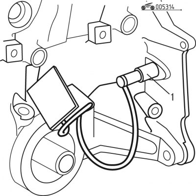
Pic. 3.14. Installation in the hole in the cylinder block stopper 0132-P flywheel: 1 - flywheel stopper
32. Install stopper 1 in the hole in the cylinder block (pic. 3.14) flywheel.
Warning! Operations pp. 33-37 - only for engines with an aluminum alloy cylinder block.
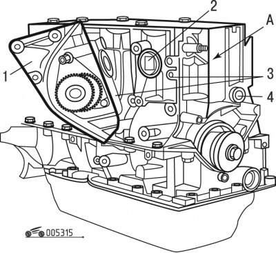
Pic. 3.15. Removing the cooling pump on engines with an aluminum alloy cylinder block: 1 - pump of the cooling system; 2 - sealing ring; 3 - centering pins of the cooling system pump; 4 - plug of the oil channel; A - cylinder block
33. Turn away bolts of fastening and remove a cover with the pump 1 (pic. 3.15) cooling systems.
34. Remove the centering pins of the cooling system pump from the cylinder block.
35. Remove the o-ring.
36. Remove the cooling system pump.
37. Remove the oil channel plug.
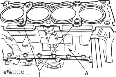
Warning! Operations pp. 38-39 - only for engines with a cast-iron cylinder block.
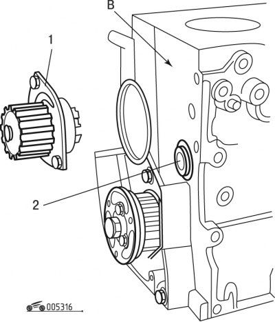
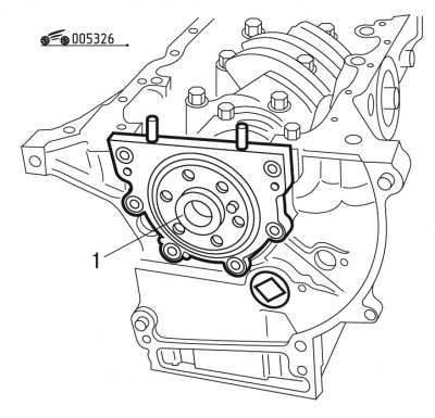
Pic. 3.16. Removing the cooling system pump on engines with a cast-iron cylinder block: 1 - pump of the cooling system; 2 - plug of the oil channel; B - cast iron cylinder block
38. Turn away bolts of fastening and remove the pump 1 (pic. 3.16) cooling systems.
39. Remove the plug 2 of the oil channel.
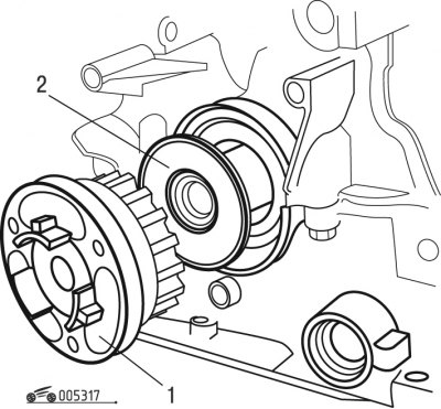
Pic. 3.17. Removing the crankshaft sprocket: 1 - a gear pulley of a cranked shaft; 2 - distance washer
40. Turn away a bolt of fastening and remove a toothed pulley 1 (pic. 3.17) crankshaft.
41. Remove spacer 2 from the crankshaft shank.
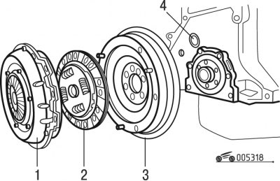
Pic. 3.18. Removing the crankshaft flywheel: 1 - cover with pressure plate assembly; 2 - driven clutch disc; 3 - flywheel; 4 - plug oil channel
If the clutch was not removed during disassembly of the power unit, then remove the clutch cover with the pressure plate assembly and the clutch disc (pic. 3.18).
42. Remove the mounting bolts and remove the flywheel 3 from the crankshaft.
43. Remove the plug 4 of the oil channel.
Warning! Operations pp. 44-61 - only for engines with an aluminum alloy cylinder block.
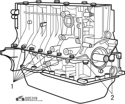
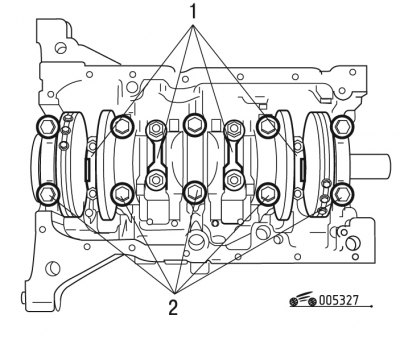
Pic. 3.19. Unscrewing the bolts securing the housing of the lower covers of the main bearings of the crankshaft from the cylinder block: 1 - bolts for fastening the housing of the lower covers of the main bearings of the crankshaft to the cylinder block; 2 - bolts for fastening the housing of the lower covers of the main bearings of the crankshaft to the cylinder block
44. Turn away from the block of cylinders bolts of fastening of the case of the lower covers of main bearings of a cranked shaft (pic. 3.19).
45. Turn the engine over with the crankcase up.
46. Turn away nuts and bolts of fastening of the pallet.
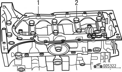
Pic. 3.20. Removing the oil pan of the cylinder block: 1 - pallet fastening nuts; 2 - pallet mounting bolts; 3 - oil pan
47. Remove pan 3 (pic. 3.20).
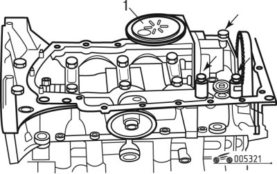
Pic. 3.21. Removing the oil pump: 1 - oil pump with oil receiver
48. Turn away bolts of fastening of the oil pump and remove the oil pump 1 (pic. 3.21) with oil receiver.
49. Remove the oil pump centering pin.
Pic. 3.22. Removing the housing of the lower covers of the main bearings of the crankshaft: 1 - housing of the lower covers of the main bearings of the crankshaft; 2 - fixing bolts
50. Turn away fixing bolts 2 (pic. 3.22) and remove the crankshaft main bearing cap housing.
51. Remove the engine crankshaft oil seal (from the gas distribution mechanism).
52. Remove the engine crankshaft oil seal (from the flywheel side of the crankshaft).
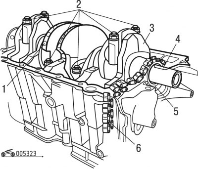
Pic. 3.23. Removing the crankshaft: 1 - thrust half rings of the crankshaft; 2 - connecting rod covers; 3 - crankshaft; 4 - key; 5 - oil pump drive gear; 6 - oil pump drive chain
53. Remove gear 5 (pic. 3.23) and oil pump drive chain.
54. Remove the key from the groove of the crankshaft.
55. Turn away nuts of rod bolts, remove covers of rods.
56. Remove the crankshaft from the seats of the main bearings.
57. Take out the top loose leaves of radical bearings of a cranked shaft.
58. Remove the thrust washers from the middle bearing of the crankshaft.
Note. Mark the connecting rod cap bearings before removing them so that they can be reinstalled in the same places during reassembly.
Pic. 3.24. Removing the clamping plates holding the cylinder liners (tool 0132-A1Z): 1 - set of clamping plates for holding cylinder liners (tool 0132-A1Z); 2 - cylinder liners
59. Remove clamping plates 1 (pic. 3.24), holding the cylinder liners.
60. Remove the liners from the cylinder block together with the pistons and connecting rods attached to the pistons. If the sleeves are to be reused, then mark their location in the cylinder block.
Warning! Operations pp. 61-79 - only for engines with a cast-iron cylinder block.
61. Thoroughly clean all mating surfaces with D2 to remove metal residue.
62. Turn away nuts and bolts of fastening of the pallet.
Pic. 3.25. Removing the oil pan of the cylinder block and oil pump: 1 - front crankshaft oil seal; 2 - holder of the front crankshaft oil seal; 3 - key; 4 - oil pan; 5 - oil pump with oil receiver; 6 - oil pump centering pin
63. Remove pan 4 (pic. 3.25).
64. Remove the holder of the front crankshaft oil seal.
65. Remove the front oil seal from the holder.
66. Turn away bolts of fastening of the oil pump and remove the pump with an oil receiver.
67. Remove the oil pump centering pin.
68. Remove the gear and oil pump drive chain.
69. Remove the key from the groove of the crankshaft.
Pic. 3.26. Removing the crankshaft rear oil seal holder: 1 - crankshaft rear oil seal holder
70. Turn away bolts of fastening and remove the holder 1 (pic. 3.26) rear crankshaft seal.
71. Remove the rear oil seal from the holder.
Note. Mark the bearings and connecting rod caps before removal so that they can be reinstalled in the same places during reassembly.
Pic. 3.27. Removing the crankshaft: 1 - connecting rod covers; 2 - bolts of covers of main bearings of a cranked shaft
72. Unscrew the nuts of the connecting rod bolts, remove the covers 1 (see fig. 3.27) connecting rods.
73. Turn away bolts 2 fastenings of covers of radical bearings of a cranked shaft and remove covers together with lower loose leaves.
Note The crankshaft main bearings are marked 1 to 5, mark 1 (first bearing) located on the flywheel side of the engine.
74. Remove the thrust half rings from the main bearing socket No. 2 (they are located in the cylinder block).
75. Remove the crankshaft from the main bearing beds.
76. Remove from the beds the upper shells of the main bearings.
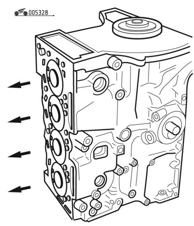
Pic. 3.28. Removing pistons with connecting rods (the arrows indicate the direction in which the pistons must be removed)
77. Establish the block of cylinders, as is shown in fig. 3.28.
78. Remove the pistons complete with connecting rods, having previously marked their location in the cylinder block (if they are to be reused during engine assembly).
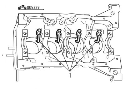
Pic. 3.29. Removing the piston crown oil cooler nozzles: 1 - nozzles for oil cooling of the piston bottom
79. Remove nozzles 1 (see fig. 3.29) oil-cooled piston crown.