
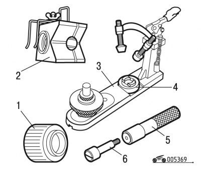
Pic. 3.69. Special tools and fixtures for assembling the connecting rod and piston group: 1 - sleeve for installing the piston in the correct position; 2 - emphasis for installing the piston pin; 3 - device for pressing the piston pin; 4 - piston stop; 5 - handle; 6 - piston pin guide
To connect the pin to the connecting rod, you will need a special tool and fixtures (pic. 3.69).
Numbers of special tools and devices for disassembling the engine according to the spare parts catalog:
- piston pin press tool - 0139-AZ;
- piston stop - 0139-Q (for TU9 engines), 0132-D3Y (for motors TU1—TU2—TU3—TU5);
- piston pin guide - 0139-P;
- handle - 0139-N;
- stop for installing the piston pin - 0132-D2Z.
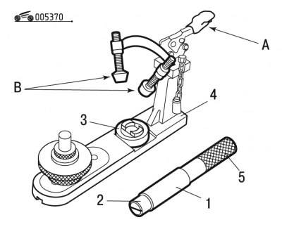
Pic. 3.70. Piston pin press tool: 1 - piston pin; 2 - guide element of the piston pin; 3 - piston stop; 4 - fixture; 5 - handle; A - clamp; B - screws
Set finger 1 (pic. 3.70) the first piston on the guide element 2.
Turn the handle by hand until it stops, without applying much force.
Place stop 3 on the finger.
Open clip A.
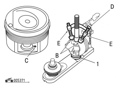
Pic. 3.71. Installing the piston in the piston pin press tool: 1 - piston stop; B - screws; C - boss; D - rod; E - lock nuts
Loosen screws B completely.
Note. When installing the piston on the stop, turn it with boss C up (pic. 3.71).
Set piston to stop 1.
Insert rod D.
Tighten screws B until the piston touches.
Tighten lock nuts E.
Tighten rod D to fix the piston.
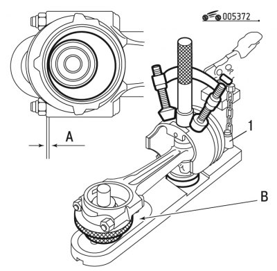
Pic. 3.72. Installing the connecting rod in the fixture: 1 - rod; A - gap; Point blank
Insert connecting rod assembly with cover (without insert) into the piston and center it with the tool (pic. 3.72).
Adjust the position and height of stop B under the connecting rod so that gap A is 0.1 mm.
Remove the connecting rod.
Install the connecting rods to the electric heater.
Place a pinch of tin powder into each upper end of the connecting rod.
Heat the connecting rods until the tin melts (up to approximately 250°C).
Lubricate the piston pins before installing them.
Try to install the piston pin into the piston bore in one motion.
Remove remaining drops of tin.
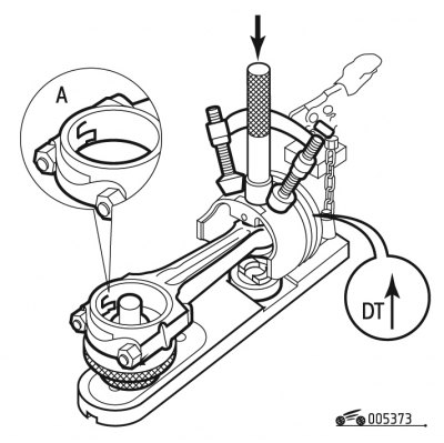
Pic. 3.73. Piston with connecting rod orientation
When assembling the piston with the connecting rod, the marking mark «DT» must be directed upward (pic. 3.73).
Insert the connecting rod into the piston, while the lock A of the connecting rod bearings must be oriented with respect to the piston, as shown in fig. 3.73.
Note. When installing on the engine, the lock of the liners A must be directed towards the exhaust manifold.
Quickly insert the piston pin until it stops.
Wait a few seconds before removing the piston and connecting rod assembly from the tool.