



- calibrated pins for fixing camshafts - 0189-A;
- camshaft seal installation tool;
- tube with tip for valve - SHRADER 0141-T1.
Remove the camshafts in the following order:
- remove the engine protective cover;
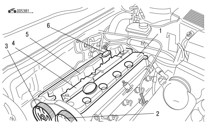
Figure 3.81. Removing the cylinder head covers: 1, 5 - lids; 2, 3 - camshaft pulleys; 4 - ignition coils; 6 - sensor
- remove pulleys 2 and 3 (figure 3.81) camshafts;
- remove compact coil block 4 ignition;
- remove sensor 6;
- unscrew the bolts securing the cylinder head covers 1 and 5 (unfold one by one in a spiral, starting from the outside);
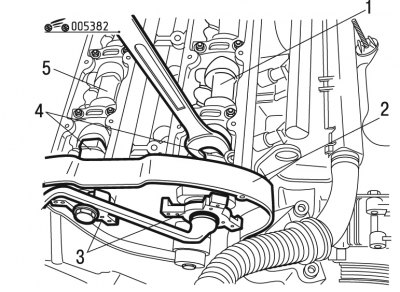
Figure 3.82. Removing the camshafts: 1, 5 - camshafts; 2 - crankcase; 3 - hubs; 4 - bald spots
- lock camshafts 1 and 6 with a 24 mm wrench (figure 3.82), setting the key to the flats 5;
- loosen the tightening torque of the bolts on both camshafts;
- remove hubs 3;
- remove crankcase 2;
- gradually unscrew the mounting bolts of the camshaft journal housing in a spiral from the middle to create a gap of several millimeters between the mating surfaces;
- completely unscrew the mounting bolts of the bed frame and remove it;
- remove the camshafts by applying leverage to each camshaft from the flywheel side to separate the timing side pilot bearing;
- remove the valve lifters, marking them first so that they can be installed in their original position during assembly;
- remove oil from the threaded holes for fastening the camshaft journal housing.
Install the camshafts in the following order:
(Source of the article is website: PeugeotBook.ru)
- lubricate the valve lifters with engine oil;
- install the pushers without mixing them up;
- make sure the tappets in the cylinder head rotate freely;
- lubricate the surfaces of the crankcase under the camshaft bearings with engine oil;
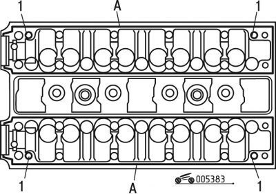
Figure 3.83. Applying sealant to the cylinder head: 1 - mounting pins; A - strip of sealant
- check for the presence of dowel pins 1 (figure 3.83);
- correctly install both camshafts in the cylinder head;
- apply a bead of SILICONE CATEGORIE 2 sealant around the entire perimeter of the mating surface of the gaskets, as well as into the threaded holes for the mounting bolts;
- install the camshaft journal housing, which has a hole for the sensor 6 (see figure 3.81) from the exhaust system;
- install the housing of the journal beds of the second camshaft;
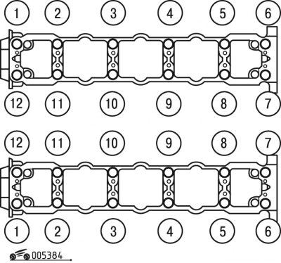
Figure 3.84. Sequence of tightening the bolts for fastening the camshaft journal bed housings
- pre-tighten the mounting bolts of both crankcases to a torque of 5 Nm in the order shown in Figure 3.84;
- finally tighten the mounting bolts to a torque of 10 Nm in the same sequence;
- install the protective crankcase of the timing mechanism;
- before installing the camshaft seals, make sure there is no sealant residue in the seat;
- install new seals using the tool;
- tighten the hub mounting bolts 3 (see figure 3.82) on the camshafts with a torque of 75 Nm, holding the shafts from turning with a wrench;
- install covers 1 and 5 (see figure 3.81) cylinder heads in a set with sealing gaskets;
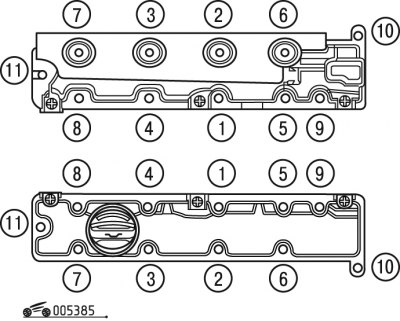
Figure 3.85. Sequence of tightening the cylinder head cover bolts
- tighten the cover mounting bolts in the sequence shown in Figure 3.85, at the first stage with a torque of 5 N·m and at the second stage with a torque of 11 N·m;
- complete the installation in the reverse order of removal;
- conduct computer programming.