
- crankshaft locking tool - 0189-B;
- devices for installing camshaft hubs - 0189-AZ;
- belt support - 0189-K;
- pin for installing a dynamic tensioner - 0189-J;
- front wheel hub lock - 0606-A1Y; 0606-A2.
Remove the toothed belt in the following order:
- remove the front right wheel;
- remove the mudguard on the right;
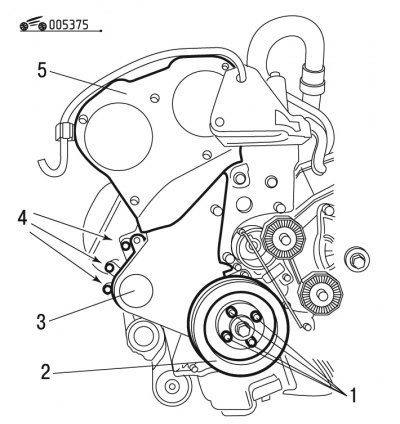
Pic. 3.75. Removing the covers of the gas distribution mechanism: 1, 4 - bolts; 2 - auxiliary drive pulley; 3, 5 - covers
- unscrew bolts 1 (pic. 3.75);
- remove the pulley 2 of the auxiliary drive;
- remove covers 3 and 5 of the gas distribution mechanism;
Warning! Do not unscrew bolts 4 fastening.
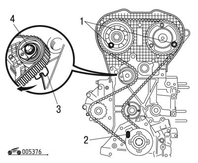
Pic. 3.76. Removing the toothed belt: 1, 2 - fixtures; 3 - bracket; 4 - bolt
- lock the flywheel with tool 2 (pic. 3.76);
- lock the camshafts with tool 1;
- loosen the tightening torque of bolt 4 as much as possible;
- release the roller bracket 3 from the crankcase tide in order to increase freedom of movement and remove the toothed belt.
Install the toothed belt in the following order:
Note. Systematically replace the timing belt.
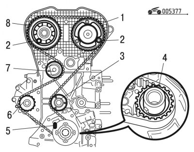
Pic. 3.77. Toothed belt installation: 1, 4, 8 - pulleys; 2, 5 - fixtures; 3, 6, 7 - rollers
- before installation, make sure that rollers 3 and 7 (pic. 3.77) and roller 6 of the water pump drive rotate freely. Also make sure the rollers don't make noise;
- install roller 3 and tighten to 35 Nm;
- put the toothed belt on the pulley 4 of the crankshaft, observing the direction of its installation;
- secure the belt with the tool.
The final tension of the belt is carried out in the following order:
Note. Carry out this operation on a cold engine.
Pic. 3.78. Roller Bracket Installation: 1 - bracket; A - crankcase tide
- install bracket 1 (pic. 3.78) roller on the tide A of the crankcase;
- remove the belt fixing device;
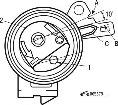
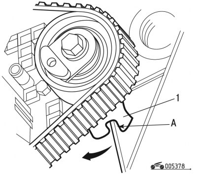
Pic. 3.79. Toothed belt tension: 1 - hex head; 2 - roller; A - the position of the nominal tension of the belt; B - the position of the maximum tension of the belt; C - tensioner mark
- rotate roller 2 (pic. 3.79) using the hex head 1 in the direction of the arrow until aligned with mark C, so that the belt tension is maximum;
- install the device in this position;
- turn roller 2 in the opposite direction of the arrow using the hexagon head until the slider lightly touches the pin;
Warning! Roller 2 must not be turned a full turn.
Note. This operation allows you to set mark C to position A, corresponding to the nominal tension.
- tighten bolt 4 (see fig. 3.76), while holding the roller with hex head 1 (see fig. 3.79), torque 20 Nm;
- remove fixtures;
- turn the crankshaft 10 revolutions in the direction of its rotation.
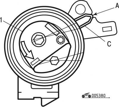
Pic. 3.80. Belt tension control: 1 - roller; A - control position; C - tensioner mark
Check the belt tension in the following order:
- check the position of mark C on the tensioner;
- if the tensioner mark is not in position A, start over the belt tensioning steps by installing the timing belt.