
Aluminum Alloy Block Engines
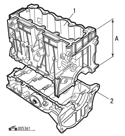
Pic. 3.61. Aluminum alloy cylinder block: 1 - cylinder block; 2 - housing of the lower covers of the main bearings of the crankshaft
Cylinder block of engines with a working volume of 1.1; 1.4 l is cast from aluminum alloy and heat treated. Holes for installing cylinder liners are made in the upper and middle parts of the block. In the lower part of the sleeve there is a polished belt, in which a groove is made for installing a sealing rubber ring. The seal at the top is provided by the cylinder head gasket. The height of the cylinder block A is given in fig. 3.61. The height of the cylinder block for various engines is given in Table. 3.5.
Table 3.5. Block height
| engine's type | A±0.05mm |
| TU9-TU1-TU2.4 | 187,48 |
| TU3-TU2J2 | 206,98 |
Warning! The housing of the lower main bearing caps is machined together with the cylinder block. Therefore, the cases are not interchangeable. Installation on the block of cylinders of the case of the lower covers of radical bearings from other engine is not allowed.
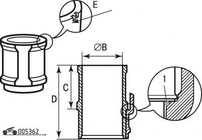
Pic. 3.62. Cylinder liner: 1 - cylinder liner sealing ring
The tightness of the cylinder block is ensured by a rubber sealing ring 1 (pic. 3.62).
Cylinder liner diameters (size B) divided into 3 classes. Sleeve class can be determined (see callout E) two ways:
- by stroke (notch), applied on the end of the sleeve from above;
- by inscription (letter+stroke).
Class identification:
- class A sleeve - inscription or one stroke;
- class B sleeve - an inscription or two strokes;
- class C sleeve - an inscription or three strokes.
Warning! When assembling the engine in sleeves, pistons of the same class as the sleeve should be installed.
The dimensions of the cylinder liner are given in tab. 3.6.
Table 3.6. Cylinder Liner Dimensions
Engine code | Size (inner diameter) B (see fig. 3.62), mm | Size (height) (see fig. 3.62), mm | |||
class A | class B | class C | C | D | |
TU9 | from 70 to 70.01 | from 70.01 to 70.02 | from 70.02 to 70.03 | 85+0,030 | |
TU1 | from 72 to 72.01 | from 72.01 to 72.02 | from 72.02 to 72.03 | ||
TU2J2-TU3 | from 75 to 75.01 | from 75.01 to 75.02 | from 75.02 to 75.03 | 90±0,015 | 135,4 |
TU2.4 | 85+0,030 | 120,9 | |||
The flatness tolerance of the cylinder block is 0.05 mm.
Engines with cast iron cylinder block
The cylinder block of engines with a working volume of 1.6 liters is made of special low-alloy cast iron, the cylinders are made directly in the block.
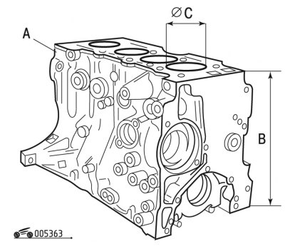
Pic. 3.63. Cast iron cylinder block
Callout A (pic. 3.63): identification mark (R1), engraved on the cylinder block - repair size. Some dimensions of the cast iron cylinder block are given in Table. 3.7.
Table 3.7. Cast Iron Block Dimensions
Engine code | Size (inner diameter) WITH (pic. 3.63), mm | Nominal size (height) IN (pic. 3.63), mm | ||
nominal | repair | |||
TU3 | 75 | 75,4 | 265,23 | |
TU5 | 78,5 | 78,9 | ||
It is possible to bore cylinders for repair pistons. After boring the cylinders, their surfaces must be honed.
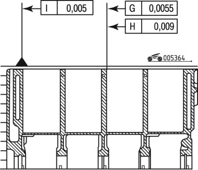
Pic. 3.64a. Tolerance of the shape and position of the cylinders in the block: G - deviation of the axis of the cylinder from the vertical; H - compliance with the norm of the cylinder shape; I - flatness
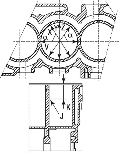
Pic. 3.64b. Cylinder wall hardness measurement: J - the location of the ball; K=50mm; a=60°
Measure diameters in V, X, Y, Z directions (pic. 3.64b).
measured values (in mm) should be in the range:
- for TU3 motors: 75 =< V, X, Y, Z =< 75.018;
- for TU5 motors: 78.5 =< V, X, Y, Z =< 78.518.
The maximum spread between 12 measurements is 0.018 mm.
The main bearing caps are machined together with the cylinder block. Therefore, they are not interchangeable and have marks on the outer surface to distinguish them.