
Note. The following is the procedure for dismantling TU series engines. Due to differences in engine design, there is a difference in the dismantling procedure for engines with aluminum and cast iron cylinder blocks.
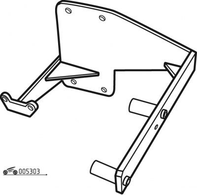
Pic. 3.3. Engine disassembly stand
On fig. 3.3 shows a stand for installing the engine during disassembly.
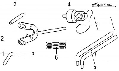
Pic. 3.4. Special tools and fixtures for engine disassembly: 1 - a device for fixing the engine flywheel; 2 - special key; 3 - a device for fixing the camshaft; 4 - flywheel stopper; 5 - levers; 6 - clamping plates for holding cylinder liners (used when dismantling engines with an aluminum cylinder block)
To ensure the convenience of disassembling the engine, a set of special tools and devices is proposed, which is shown in Fig. 3.4.
Numbers of special tools and devices for disassembling the engine according to the spare parts catalog:
- engine flywheel fixing tool - 0132-QZ;
- special key - 0132-AA;
- camshaft fixing tool - 0132-R;
- levers - 0153-Q;
- flywheel stopper - 0132-P;
- clamping plates for holding cylinder liners - 0132-A1Z.