
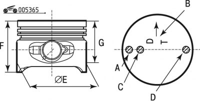
Pic. 3.65. The main dimensions of the piston and the marks applied to the piston
The piston is cast aluminium. The outer diameter of the pistons are divided into three classes (A, B, C) through 0.01 mm. The outer surface of the piston has a complex shape. Therefore, it is necessary to measure the piston diameter only in a plane perpendicular to the piston pin, at a certain distance from the piston crown. The main dimensions of the piston are shown in fig. 3.65 and in table. 3.8, 3.9.
- mark A: mark for oversized pistons;
- mark B: mark oriented towards the timing gear;
- mark C: piston identification mark;
- mark D: class marking to ensure a non-dismantling pair with a sleeve (3 classes).
Table 3.8. The main dimensions of the pistons of the 1st generation engines
Parameter | Engine code | ||
TU9 | TU1 | TU2-TU3 | |
Size, mm: | Engines: aluminum alloy cylinder block | ||
d E class A | from 69.94 to 69.95 | from 71.94 to 71.95 | from 74.95 to 74.96 |
d E class B | from 69.95 to 69.96 | from 71.95 to 71.96 | from 74.96 to 74.97 |
d E class C | from 69.96 to 69.97 | from 71.96 to 71.97 | from 74.97 to 74.98 |
F | 58 | 64,05±0,15 | 64±0,05 |
G | 11 | 13 | 10 |
Engine code | ||
TU3F-TU3J2 | TU5 | |
Size, mm: | Engines: cast iron cylinder block | |
d E (denomination) | 74,96 | 78,455+0,015 |
d E (repair size 1) | 75,36 | 78,855+0,015 |
F | 64±0,05 | 57,5 |
G | 11 | |
Table 3.9. The main dimensions of the pistons of the 2nd generation engines
Parameter | Engine code | |||||
TU1/K | TU1M+ | TU1JP | ||||
Size, mm: | Engines: aluminum alloy cylinder block | |||||
d E class A | from 71.95 to 71.959 | |||||
d E class B | from 71.960 to 71.969 | |||||
d E class C | from 71.970 to 71.980 | |||||
F | 47,5±0,15 | |||||
G | 8 | |||||
Label C | 1Z | 1X | 1Y | | ||
Engine code | ||||||
TU3JP/L3 | TU3JP/K | TU3JP/L4 | | |||
Size, mm: | Engines: aluminum alloy cylinder block | |||||
d E class A | from 74.95 to 74.959 | |||||
d E class B | from 74.960 to 74.969 | |||||
d E class C | from 74.970 to 74.980 | |||||
F | 49,75±0,15 | |||||
G | 8 | |||||
Label C | 3Y | 3Z | 3X | | ||
Engine code TU5JP | ||||||
Size, mm: | - | |||||
d E (denomination) | 78,455+0,015 | |||||
d E (repair 1) | 78,855+0,015 | |||||
F | 57,5 | |||||
G | 11 | |||||
Label C | JP+ | - | - | | ||
Attention! Pistons are supplied complete with piston pins; replacement of piston rings with rings from another piston is not allowed.
Piston rings are made of special cast iron. The top compression ring is with a chrome-plated barrel-shaped outer surface. The lower compression ring is a scraper type. Oil scraper ring - with chrome-plated working edges and a twisted expanding spring.
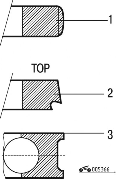
Pic. 3.66. Piston rings: 1 - top compression ring; 2 - lower compression ring; 3 - oil scraper ring
The top compression ring 1 is shown in fig. 3.66 (installation direction does not matter). The lower compression ring 2 is set with a mark «top» up. The oil scraper ring 3 during installation can be oriented upwards on either side.
The 2nd generation engines have new improved piston rings, the rings are color coded:
- TU1 engines - orange;
- TU3 engines - purple.
Piston pin - steel, tubular section, pressed into the upper head of the connecting rod and rotates freely in the piston bosses.
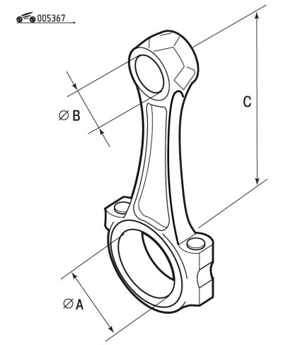
Pic. 3.67. 1st generation engine connecting rod
Connecting rod - steel, forged. The connecting rod is processed together with the cover, so they are not interchangeable individually. In order not to confuse the covers and connecting rods during assembly, they are stamped with the number of the cylinder in which they are installed. The dimensions of the connecting rods are shown in fig. 3.67 and in table. 3.10, 3.11.
Table 3.10. The main dimensions of the connecting rods of the 1st generation engines
Parameter | Engine code | |||||
TU9 | TU1-TU2.4 | TU2J2 | TU3 | TU5 | ||
Nominal size (see rice. 3.67), mm: | ||||||
d A+0,016 | 41,128 | 48,655 | | |||
d B+0,017 | 17,939 | 19,463 | | |||
C±0,07 | 122,8 | 112,3 | 133,5 | 126,8 | 133,5 | |
Table 3.11. The main dimensions of the connecting rods of the 2nd generation engines
Parameter | Engine code | ||
TU1 | TU3 | ||
Nominal size, mm: | |||
d A+0,016 | 48,655 | ||
d B+0,011 | 19,463 | ||
C±0,05 | 125,3 | 140,25 | |
Note. 1st generation TU5 engine connecting rods continue to be used on 2nd generation engines.
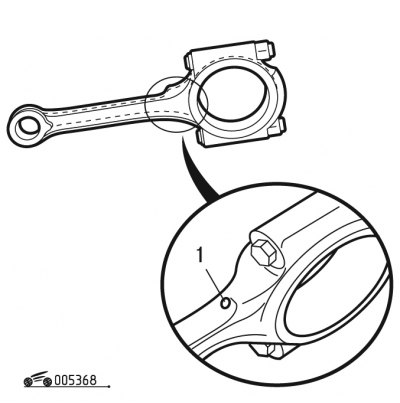
Pic. 3.68. Connecting rod for 2nd generation engines: 1 - oil splash hole
The new connecting rod has a hole (pic. 3.68) to spray oil on the inner surface of the piston.
The connecting rod also has a new bore bushing.