



Crank mechanism
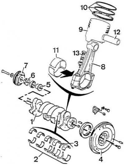
1 - crankshaft, 2 - main bearing shells, 3 - crankshaft thrust half rings, 4 - flywheel, 5 - oil pump drive sprocket, 6 - timing drive toothed pulley, 7 - V-pulley, 8 - connecting rod, 9 - piston, 10 - piston rings, 11 - connecting rod shells, 12 - piston pin, 13 - connecting rod cap bolt
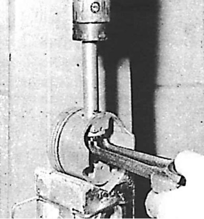
Removal the piston pin on a press on 8-valve engines
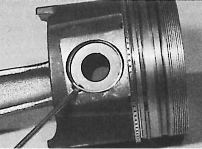
Removal the piston pin retaining ring on 16-valve engines
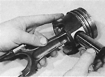
Removal the piston pin on 16-valve engines
Piston and ring wear can usually be detected by signs of increased oil consumption and low compression, sometimes associated with cylinder wear.
Another sign of piston wear is piston knocking, similar to noise from the crankshaft, which must be distinguished from bearing knocking. It can be clearly heard at low engine speeds with no load (for example, in idle mode), it is heard much less as the engine speed increases. Piston wear usually occurs in the area of the skirt or the lower end of the piston.
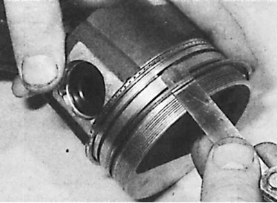
1. Remove the upper sealing ring, middle sealing ring and oil scraper ring one by one. To remove the rings, insert thin steel plates under the ring (can you use feeler gauges) in several places evenly around the perimeter of the piston and along the plates, move the piston ring off the piston.
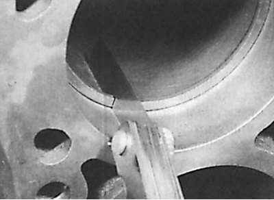
2. Check the ring lock clearance. To do this, insert all rings sequentially from the top into the cylinder working sleeve. Push the ring down into the cylinder with the piston upside down to a depth of 15 mm and measure the ring lock clearance with a feeler gauge. The ring lock clearances are not adjustable, and if the clearance increases beyond the permissible limit, the ring must be replaced.
3. Disassemble the connecting rod-piston assemblies, removing the piston pins using a press (see figure Removing the piston pin on a press on 8-valve engines and figure Removing the piston pin on 16-valve engines).
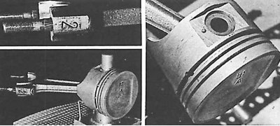
4. To remove and install piston pins, use special equipment, namely, a guide and a bracket. Install a guide device on the pin before pressing. However, do not fasten the pin to the shank before pressing, leave a gap of about 0.1 mm.
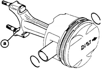
5. On engines with 16 valves, when installing the piston and connecting rod, ensure their correct relative position (a - mark on the base of the connecting rod).