



Typical piston ring placement order
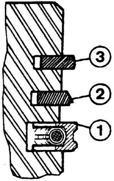
1 – oil scraper ring,
2 – second sealing ring,
3 – upper sealing ring
Installing the piston into the cylinder liner using a special piston ring holder
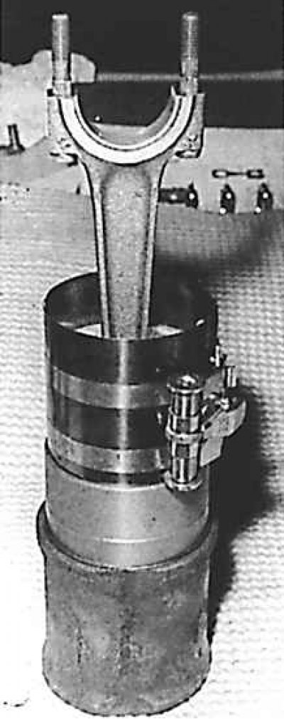
Install the piston on the device so that the "drop" on its side surface faces upward. The arrow on the piston bottom should also face upward. Install the connecting rod accordingly.
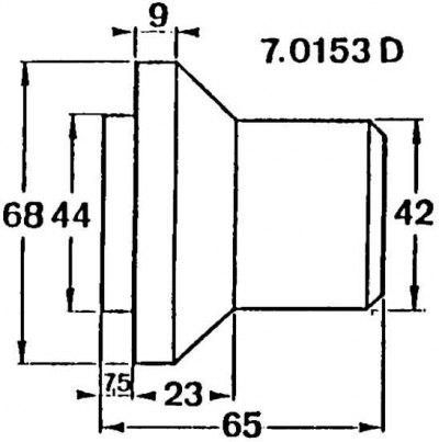
Dimensions of the crankshaft seal ring mandrel on the camshaft side
Assembly
1. Place the connecting rod on the heater so that the connecting rod heads are heated and the connecting rod bases are insulated with a heat-resistant plate or other means; place a piece of solder on the connecting rod head as a temperature sensor.
2. Turn on the power of the heater, turn off the power when the solder starts to melt.
3. The following steps must be taken quickly:
- remove the solder drop from the first connecting rod and prepare the connecting rod for installation;
- wait at least 10 seconds, then lift the connecting rod and remove the entire assembly;
- remove the tailstock and then do the same for the remaining connecting rods;
- install rings on each piston (see figure Typical piston ring arrangement);
- position the ring locks on the piston at an angle of 120°.
4. The installation of the oil scraper ring locks should be as follows: the lock of each link should be on each side of the piston pin, 30–50 mm on both sides, the spring cut should be exactly on the axis.
[Original is located at: Peugeotbook.ru]
5. The installation of the sealing ring (upper) and the sealing (second) must be such that their locks are offset by 120° relative to the spring and do not coincide. The sealing rings must be installed with the inscription "TOP" facing upwards.
Attention! Do not mix up the sealing rings, as the upper and second sealing rings have different profiles.
6. Place the pistons in pairs with the cylinder liners. A special ring cage should be used. When installing, it is necessary to observe the installation marks. The arrow on the piston should be directed towards the camshaft drive, and the mark on the cylinder liner (in case of installation) - on the same side as before removal.
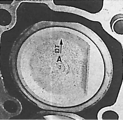
7. Install the cylinder liners together with their round sealing rings in the cylinder block. If the liners are re-installed, their position relative to the cylinder block must be maintained. The pistons must be installed so that the arrow points towards the camshaft drive. When installing the pistons in the cylinder, pre-compress the piston rings with a mandrel (see picture Installing the piston into the cylinder liner using a special piston ring holder).
8. Install the connecting rod caps with liners and tighten them to the required torque.
9. Install the oil pump sprocket along with the key and chain onto the crankshaft.
10. On the camshaft drive side, install the main bearing cap, lubricated with Loctite.
11. Using a special 0.153D mandrel, install the sealing ring (see figure Dimensions of the crankshaft seal ring mandrel on the camshaft side).
12. Place the chain on the oil pump, place a support under the pump. Secure the pump.
13. Secure the oil pan together with its gasket.
14. Install the crankshaft in the timing position: the key must face the coolant pump and be installed horizontally.
15. Remove the installation element. Using, for example, a pin punch, hold it so that it protrudes above the surface of the cylinder block and install the cylinder head.
16. Install the timing belt and adjust its tension.