



Table of contents: Connecting rod and main bearings 🠇 Determining the size of the liners 🠇 Checking the working clearance in…🠇
Attention! Some early engines use old type bolts in the cylinder head, i.e. hexagonal head bolts. In case of assembly of the cylinder liner-piston unit of the new type (cutout on cylinder liners) in an early production engine (without cutouts on cylinder liners) the following parts must be replaced: cylinder head bolts (Torx N55), washers for these bolts and a modified head gasket. The cylinder head tightening method specific to Torx bolts must also be followed.
Plugs that close the technological holes that must be removed for complete cleaning of the cylinder block
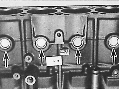
The plugs are indicated by arrows.
Never scrape the surfaces of the joints of parts made of light alloys; a special cleaning agent should be used (Magnus Magstrip or Framet Decaploc).
To completely clean the cylinder block, remove the process plugs by drilling holes in them, screwing in self-tapping screws and using the screws to remove the plugs. After cleaning the engine, install new plugs.
Regardless of the method used to clean the cylinder block, make sure that all holes and passages are completely clean and dry.
Connecting rod and main bearings
Typical defects of liners
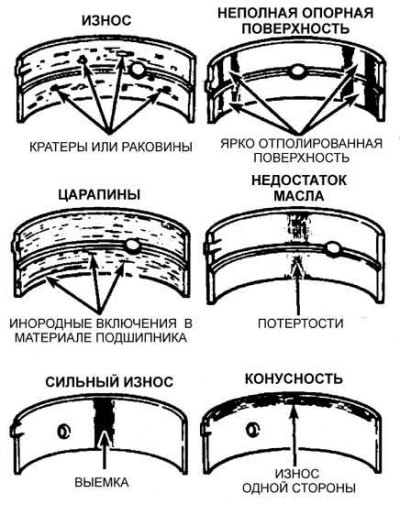
With proper maintenance and regular oil and filter changes, connecting rod and main bearings will last a very long time. A sign of damage to connecting rod bearings is a regular, rhythmic, loud knocking noise from the crankshaft. The frequency depends on engine speed. This knocking noise is especially noticeable when the engine is under load. This sign is accompanied by a drop in oil pressure, although this is usually unnoticeable unless an oil pressure sensor is installed. Damage to the main bearing is usually indicated by noticeable vibration, especially at high engine speeds, and this vibration is accompanied by a more significant drop in oil pressure and a "rumbling" noise.
Connecting rod and main bearings must be replaced, however, bearings removed from the engine must be examined, since their condition can be used to determine the condition of the engine.
Failure of connecting rod and main bearings may occur due to lack of lubrication, presence of dirt or other foreign particles, engine overload or corrosion. Before assembling the engine, it is necessary to eliminate the cause of bearing failure. One of the reasons may be operation of the engine at low speeds under high loads, when the oil pump does not create high pressure and performance, and the oil, in turn, due to the high load, is intensively squeezed out of the working area. Frequent engine starts and short trips lead to corrosion, since the engine does not warm up sufficiently to remove water and corrosive gases.
Determining the size of the liners
Location of the mark on the cylinder block and crankshaft
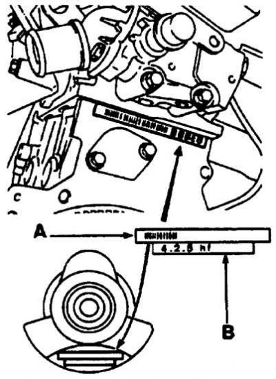
A - barcode (used for production only),
B – designation signs
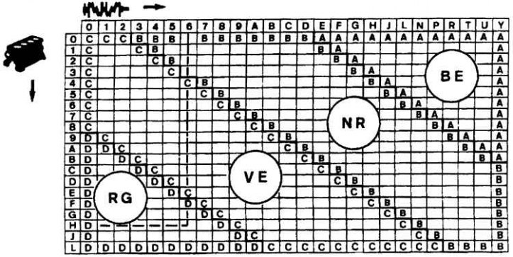
Insert Selection Chart
On early engines, the upper and lower bearings were the same thickness.
On later engines, the bearing working clearance was significantly reduced and in order to meet this condition, four different liners are used, which are designated by a color mark on the end face. The color of the mark indicates the thickness of the liners. The upper liners on all bearings have the same size, and the working clearance is adjusted by installing the lower liners of the required thickness.
Engines 1500 cm³, 1761 cm³ and 1905 cm³
Label color | Thickness (mm) | |
Standard | Repair | |
| Upper insert: | ||
| - yellow | 1,856 | 2,006 |
| Bottom liner: | ||
| - blue (Class A) | 1,836 | 1,986 |
| - black (Class B) | 1,848 | 1,998 |
| - green (Class C) | 1,859 | 2,009 |
| - red (Class D) | 1,870 | 2,020 |
Engines 1998 cm³
Label color | Thickness (mm) | |
Standard | Repair | |
| Upper insert: | ||
| - black | 1,847 | N/A |
| Bottom liner: | ||
| - blue (Class A) | 1,844 | N/A |
| - black (Class B) | 1,857 | N/A |
| - green (Class C) | 1,866 | N/A |
| - red (Class D) | 1,877 | N/A |
On the latest engines, new liners can be selected based on the markings on the cylinder block. If there are no markings, liners can only be selected by measuring the working clearance.
The cylinder block marks are on the left side of the block, and the crankshaft marks are on the end of the crankshaft web. These marks can be used to select the correct liner thickness as follows.
There are two identification lines on the crankshaft and cylinder block: a bar code used by Peugeot in production and a series of five designations. The first designation in the sequence refers to the size of the bearing number 1. The last designation in the sequence (which is accompanied by an arrow) refers to size number 5 of the insert (see figure Location of the mark on the cylinder block and crankshaft). Determine the designation number from a specific crankshaft journal and cylinder block bearing hole.
On the upper axis of the nomogram, mark the crankshaft designation and draw a vertical line through this point. On the left vertical axis of the nomogram, mark the cylinder block designation and draw a horizontal line through this point. The intersection point of the lines indicates the size of the liner to ensure the required clearance (see figure Insert Selection Diagram).
For example, the nomogram shows that the crankshaft indicates 6, the cylinder block indicates H, the intersection point within the red area determines that red (Class D) is the most suitable to obtain the required clearance.
Checking the working clearance in the crankshaft bearings
Fast (and more accurate) the method consists of using a product known as "Plastigauge". It consists of a round plastic rod that is compressed between the liner and the crankshaft journal. After removing the cover and the lower liner, the deformed plastic rod is measured with a special template, which is included in the kit "Plastigauge".
1. The crankshaft is installed without lubrication on the liners installed in the engine block. The crankshaft journals and liners must be completely clean and dry.
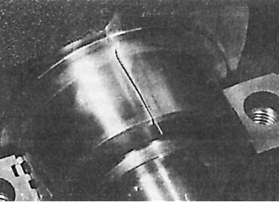
2. Cut off several pieces of plastic rod "Plastigauge" (they should be slightly shorter than the width of the main bearings) and install them on each crankshaft journal.
3. Install the covers with the lower liners and tighten the mounting bolts to the required torque. During the process of measuring the gaps using the "Plastigauge" do not rotate the crankshaft.
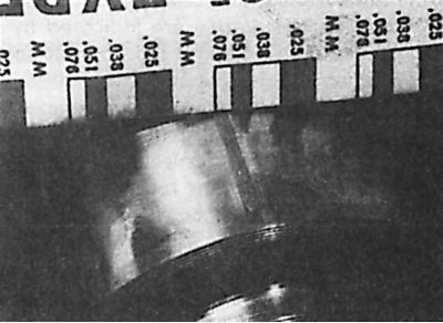
4. Unscrew the liner mounting cover, remove it and apply the scale ruler printed on the package to the deformed plastic rod. By comparing the width of the deformed plastic rod with the control width on the scale ruler, determine the size of the gap.
5. Finally, thoroughly clean all traces of Plastigauge material from the bearings and crankshaft.