



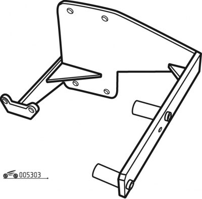
Figure 3.3. Engine disassembly stand
1. Install the cylinder block on the stand (see figure 3.3).
2. Thoroughly clean the mating surfaces and threads in the cylinder block holes.
3. Match the pistons to the cylinders by class, one group by weight and assemble the pistons with the connecting rods as specified in the subsection "Connecting rod and piston group".
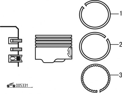
Figure 3.31. Installing piston rings: 1 - oil scraper ring; 2 - lower compression ring; 3 - upper compression ring
4. Install the piston rings using a ring clamp (figure 3.31).
Note: Rings must be installed so that the "top" mark is on the side of the ring that faces up when installed.
5. Rotate the rings in the piston grooves so that the compression ring joints are rotated 120° relative to the oil scraper ring joint.
6. Lubricate the piston with engine oil.
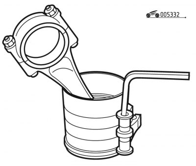
Figure 3.32. Installing a mandrel on the piston to install the piston into the cylinder liner
7. Place a mandrel on the piston assembly with the connecting rod to install the piston into the cylinder liner (figure 3.32).
8. Tighten the mandrel clamps with medium force.
9. Install the mandrel with the piston on the sleeve so that the piston can be mounted in the sleeve.
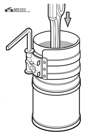
Figure 3.33. Installing the piston assembly with the connecting rod into the cylinder liner
10. Applying force to the connecting rod in the direction indicated by the arrow (figure 3.33), insert the piston with rings into the cylinder sleeve so that the piston is completely (with some reserve) came out of the frame.
Note: If reused, liners must be installed in the cylinder block in the same locations they were in before disassembly (in accordance with the marks applied during engine disassembly). The pistons must be oriented in the cylinder liners so that the marks on the pistons (arrows) are directed towards the valve timing drive.
11. Install the remaining pistons together with the connecting rods into the corresponding cylinder liners in a similar manner.
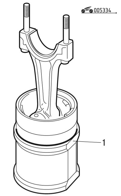
Figure 3.34. Installing the cylinder liner sealing ring: 1 - cylinder liner sealing ring
12. Install a new sealing ring 1 on each sleeve (figure 3.34), making sure that it is not twisted.
13. Install the bearing shells into the connecting rods.
14. Install the assembled units: sleeves, connecting rods, pistons into the cylinder block, observing the installation marks made during disassembly or checking the protrusion of the sleeves.
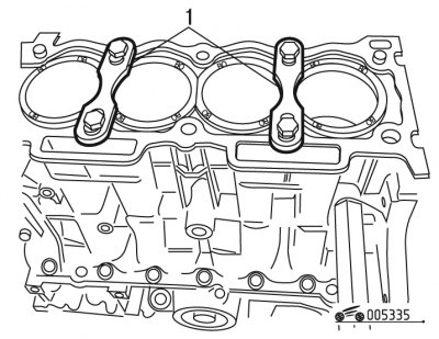
Figure 3.35. Installing clamping plates on the cylinder block to hold the cylinder liners (fixture 0132-A1Z): 1 - set of clamping plates for holding cylinder liners (fixture 0132-A1Z)
15. Install kit 1 (figure 3.35) clamping plates that hold the cylinder liners. The plates are mounted on bolts that are screwed into the holes for the cylinder head mounting bolts.
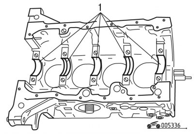
Figure 3.36. Installation of crankshaft main bearing shells in the cylinder block bed: 1 - upper crankshaft main bearing shells
16. Install the liners with grooves in the 2nd and 4th beds of the cylinder block, and in the 1st, 3rd and 5th beds of the cylinder block (and in the main bearing caps) - liners without grooves (figure 3.36).
Notes:.
- 1. Select the main bearing shells as specified in the "Crankshaft and Flywheel" subsection.
- 2. Main bearings 1-3-5 of the crankshaft have smooth liners (from the cylinder block and bearing cap side).
- 3. Main bearings 2-4 of the crankshaft have liners with grooves (from the cylinder block and bearing cap side).
17. Lubricate the crankshaft bearings and journals.
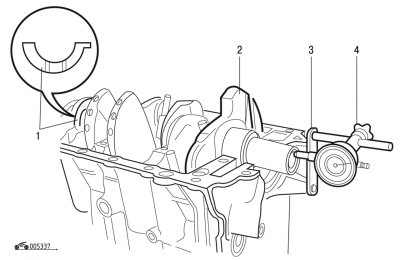
Figure 3.37. Measuring the crankshaft axial clearance: 1 - crankshaft thrust half rings; 2 - crankshaft; 3 - pointer indicator support rod (the part number of the device according to the spare parts catalog is 0117-AH); 4 - support for pointer indicator 0118-FZ
18. Place crankshaft 2 in the main bearings (figure 3.37) and insert the thrust half rings into the bed of the middle main bearing.
Note: The half rings must be facing the grooves towards the thrust surfaces of the crankshaft (an antifriction layer is applied to the surface of the half ring from the groove side).
19. Check the axial clearance of the crankshaft. To do this, install a stand with a dial indicator on the cylinder block so that rod 3 (see figure 3.37) indicator rested against the crankshaft flange. Moving the shaft back and forth (for example, using screwdrivers), measure the axial clearance with an indicator. It should be within 0.07-0.27 mm. If the clearance is larger, then bring it back to normal by replacing the old thrust half rings with new ones or installing half rings of increased thickness.
20. Lubricate with engine oil and install the connecting rod bearings.
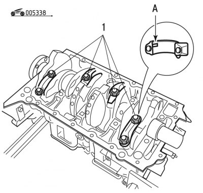
Figure 3.38. Installing the connecting rod caps: 1 - connecting rod caps; A - recess in the connecting rod cover
21. Install the connecting rods and their caps 1 (figure 3.38) on the crankshaft journals, tighten the connecting rod bolts.
Warnings!
- 1. When assembling the connecting rods, it is necessary to use new connecting rod bolt nuts each time.
- 2. Connecting rod caps must be installed so that the cylinder number on the cap is opposite the cylinder number on the lower connecting rod head; notches (A) (see figure 3.38) the connecting rod bearing shells must fit into the recesses in the connecting rod caps.
22. Tighten the connecting rod bolt nuts to 38 N·m.
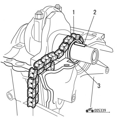
Figure 3.39. Installing the oil pump drive gear: 1 - oil pump drive chain; 2 - oil pump drive sprocket key; 3 - oil pump drive sprocket
23. Insert the segment key 2 into the socket on the front end of the crankshaft (figure 3.39) and install the oil pump drive sprocket on the shaft.
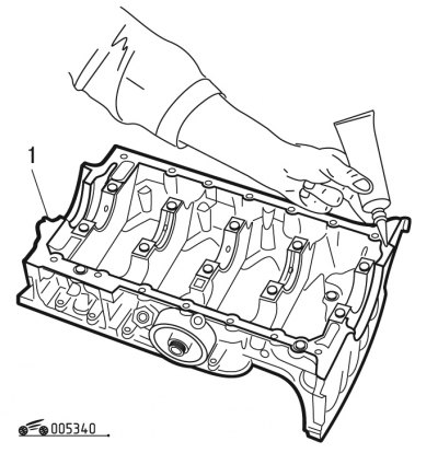
Figure 3.40. Installing the lower main bearing cap housing of the crankshaft: 1 - housing of lower main bearing caps of crankshaft
24. Install in 2 and 4 beds of case 1 (figure 3.40) the lower main bearing caps have liners with a groove, and in the 1st, 3rd and 5th beds of the lower main bearing cap housing, there are liners without a groove.
25. Lubricate the bearings with engine oil.
26. Check the presence of centering pins on the cylinder block.
27. Check the correct selection of main bearing shell pairs.
28. Apply a thin layer of sealant (E10) evenly to the connector surface.
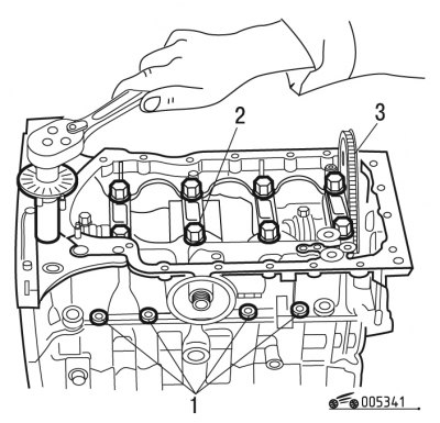
Figure 3.41. Tightening the bolts securing the lower crankshaft main bearing cap housing: 1 - housing of lower main bearing caps of crankshaft; 2 - bolts for fastening the lower main bearing caps; 3 - bolts for fastening the housing of the lower main bearing caps to the cylinder block
29. Install housing 1 (figure 3.41) lower main bearing caps on the cylinder block (from below).
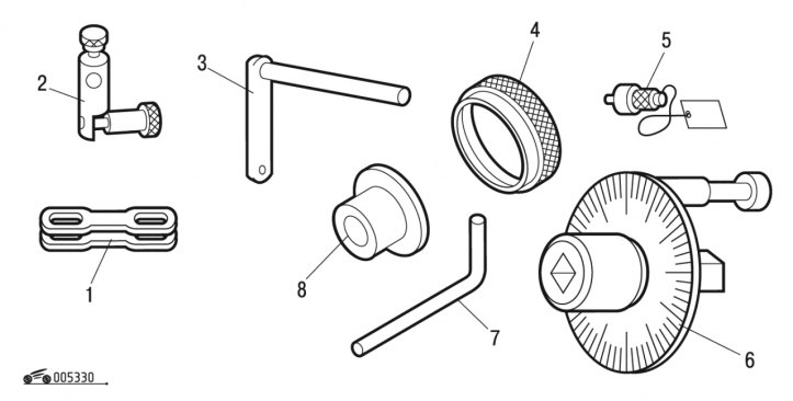
Figure 3.30. Special tool and devices for engine assembly: 1 - Clamping plates for holding cylinder liners (used when disassembling engines with aluminum cylinder blocks); 2 - pointer indicator support; 3 - pointer indicator support rod; 4 - mandrel for installing the rear crankshaft oil seal; 5 - flywheel stopper; 6 - Torque wrench with circular scale; 7 - device for fixing the engine flywheel; 8 - mounting mandrel
30. Tighten the lower main bearing cap bolts to 20 N·m, then tighten an additional 44° using a torque wrench with a dial scale (see figure 3.30) (working in a spiral, starting with the bolts located in the center).
31. Tighten the bolts 3 (see figure 3.41) fastening the housing of the lower main bearing caps to the cylinder block with a force of 8 Nm.
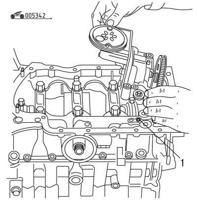
Figure 3.42. Installing the oil pump with oil receiver: 1 - oil pump centering pin
32. Check the presence of the centering pin 1 (see figure 3.42) oil pump.
33. Install the oil pump with oil receiver in place.
34. Tighten the oil pump mounting bolts to 9 N·m.
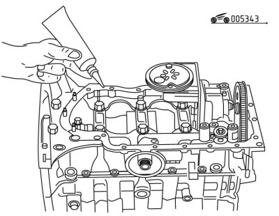
Figure 3.43. Applying sealant to the joint plane of the cylinder block and oil pan
35. Apply a thin layer of sealant (E10) evenly to the connector surface (figure 3.43).
36. Install the oil pan.
37. Tighten the oil pan mounting bolts to 0.8 N·m.
Warning: Remove any remaining sealant before reinstalling the rear crankshaft oil seal (from the flywheel side).
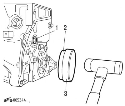
Figure 3.44. Installing the rear crankshaft oil seal: 1 - oil channel plug; 2 - rear crankshaft oil seal; 3 - mandrel for installing the rear crankshaft oil seal
38. Using a mandrel, press the new rear oil seal 2 into the hole in the cylinder block (figure 3.44) (from the flywheel side of the crankshaft).
39. Replace the oil channel plug and tighten it to a torque of 30 N·m.
40. Install the flywheel onto the engine crankshaft.
41. Apply LOCTITE FRENBLOC sealant to the flywheel mounting bolts before installation.
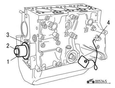
Figure 3.45. Installing the front crankshaft oil seal: 1 - mandrel for installing the front crankshaft oil seal; 2 - bolt used to install the seal; 3 - front crankshaft oil seal; 4 - flywheel stopper
42. Install stopper 4 into the hole in the cylinder block (figure 3.45) flywheel.
43. Tighten the flywheel mounting bolts to 67 Nm.
44. Using a mandrel, press a new oil seal into the hole in the cylinder block (from the timing drive side). Perform the final pressing of the seal using bolt 2, which is screwed into the hole in the end of the crankshaft.
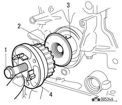
Figure 3.46. Installing the crankshaft toothed pulley: 1 - toothed pulley mounting bolt; 2 - spacer washer; 3 - key; 4 - toothed pulley of the crankshaft
45. Make sure key 3 is present (figure 3.46) in a socket at the front end of the crankshaft.
46. Apply a thin layer of sealant (E15) evenly between the crankshaft spacer washer and the key.
47. Install the crankshaft toothed pulley spacer washer.
48. Install the crankshaft toothed pulley in place.
49. Install the toothed pulley mounting bolt with washer in place.
50. Tighten the toothed pulley mounting bolt to a torque of 100 Nm.
Note: Make sure there are no traces of sealant (sealing paste) on the toothed pulley of the crankshaft.
51. Remove stopper 4 (see figure 3.45) flywheel.
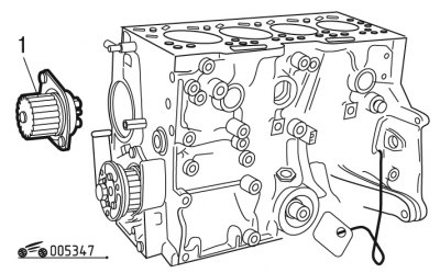
Figure 3.47. Installing the cooling system pump: 1 - cooling system pump
52. Install new pump 1 (figure 3.47) cooling systems with new gasket (the use of a used gasket is not permitted).
53. Tighten the coolant pump mounting bolts to 18 N·m.
Note: For correct installation of pump 1 (figure 3.48) two guide pins are pressed into its body, which must enter the corresponding holes in the cylinder block.
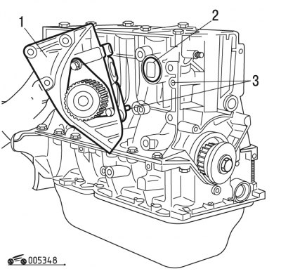
Figure 3.48. Installing the cooling system pump on engines with an aluminum alloy cylinder block: 1 - cooling system pump; 2 - sealing ring; 3 - centering pins of the cooling system pump
54. Make sure that the sealing ring 2 is present (see figure 3.48) and centering pins 3 of the cooling system pump.
55. Install the cooling system pump 1 assembly.
56. Tighten the coolant pump mounting bolts to the following torques:
- m10 bolts - 65 Nm;
- m8 bolts - 30 Nm.
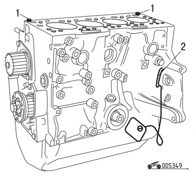
Figure 3.49. Installing bushings for centering the head on the cylinder block: 1 - bushings for centering the head on the cylinder block; 2 - device for fixing the engine flywheel
57. Turn the crankshaft so that it can be fixed using tool 2 (figure 3.49) for fixing the engine flywheel (the tool number in the spare parts catalogue is 0132-QZ).
58. Install bushings 1 in place to center the cylinder head.
59. Turn the crankshaft so that the pistons of the first and fourth cylinders are at top dead center.
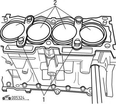
Figure 3.24. Removing the clamping plates holding the cylinder liners (fixture 0132-A1Z): 1 - set of clamping plates for holding cylinder liners (fixture 0132-A1Z); 2 - cylinder liners
60. Remove the clamping plates (see figure 3.24), holding the cylinder liners.
61. Clean the threads of the cylinder head bolt holes using an M10x150 tap.
Note: Always install a new cylinder head gasket when assembling the engine. Do not use a used gasket. Before installing the gasket, remove oil from the mating surfaces of the block and cylinder head. The gasket must be clean and dry. Do not allow oil to come into contact with the gasket surface.
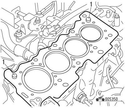
Figure 3.50. Bushings for centering the head on the cylinder block: 1 - centering bushings of the head on the cylinder block
62. Install along the centering sleeves 1 (figure 3.50) cylinder head (the name of the gasket manufacturer must be on top).
63. Install the cylinder head bolts, pre-lubricated with engine oil.
Note: Before assembling the engine, lubricate the threads and bolt heads in advance by dipping them in engine oil. Then let the excess drain off, keeping the bolts for at least 30 minutes.
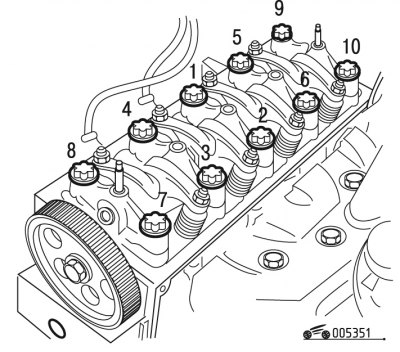
Figure 3.51. Cylinder head bolt tightening sequence
64. Tighten the cylinder head bolts in the specified sequence (figure 3.51).
65. Adjust the clearances in the valve drive mechanism.
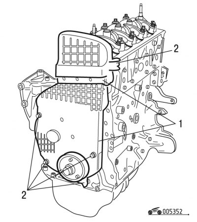
Figure 3.52. Installing the timing belt covers: 1 - Timing belt covers of the camshaft drive; 2 - bolts for fastening the covers of the toothed belt of the camshaft drive
66. Install covers 1 (figure 3.52) toothed belt of the camshaft drive.
67. Tighten the cover mounting bolts to 8 Nm.
Warning! The exhaust manifold gasket is made of stainless steel. The holes in the exhaust manifold gasket for the exhaust gases to exit have an A border (figure 3.53), when installing the gasket, its convex side (in the area of the holes) must be facing the exhaust manifold (from the holes in the cylinder block).
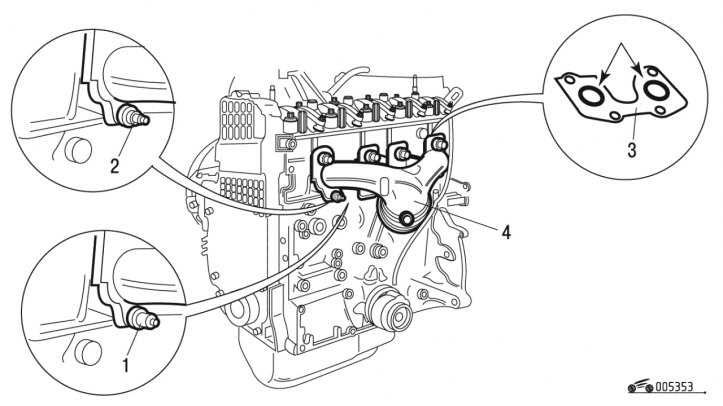
Figure 3.53. Installing the exhaust manifold: 1 - long exhaust manifold mounting nut; 2 - short exhaust manifold mounting nut; 3 - exhaust manifold gasket; 4 - exhaust manifold
68. Install gasket 3 on the studs (see figure 3.53) exhaust manifold.
69. Install the exhaust manifold onto the studs.
70. Tighten nuts 1 and 2 of the exhaust manifold.
Warning: There are two types of exhaust manifold mounting nuts: short and long.
Tighten short nut 2 to a torque of 25 Nm, tighten long nut 1 to a torque of 16 Nm.
71. Make sure that the fuel rail elements are correctly positioned and that the injector sealing rings are not damaged.
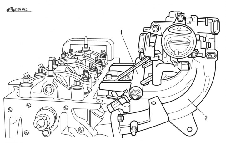
Figure 3.54. Installing the intake manifold: 1 - fuel rail with injectors; 2 - intake manifold
72. Install fuel rail 1 (figure 3.54).
73. Tighten its mounting bolts to a torque of 7 Nm.
74. Install new rubber gaskets on the intake manifold.
75. Install the intake manifold 2.
76. Tighten the intake manifold mounting bolts to 8 N·m.
77. Make sure that the fuel rail and manifold connector are positioned correctly.
78. Tighten the mounting bolts to 8 Nm.
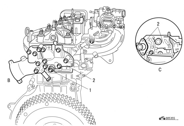
Figure 3.55. Installing the coolant temperature sensor: 1 - coolant temperature sensor; 2 - cooling system thermostat block
79. Install sensor 1 (figure 3.55) coolant temperature.
80. Tighten the sensor to 25 Nm.
81. Apply a thin layer of silicone sealant (E10) to the flange of pipe B.
82. Install a new thermostatic element into the cooling system thermostat block 2. Make sure the sealing gasket is present.
83. Apply a thin layer of silicone sealant (E10) to the sealing surfaces of both blocks.
84. Install the cooling system thermostat block 2 assembly onto the cylinder head.
85. Tighten the cooling system thermostat unit mounting bolts to 8 N·m.
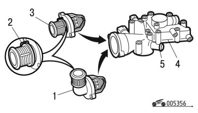
Figure 3.56. Design options for outlet pipes with a built-in thermostatic element: 1 - G-shaped outlet pipe with built-in thermostatic element (depending on the engine type); 2 - thermostatic element; 3 - straight outlet pipe with built-in thermostatic element (depending on the engine type); 4 - cooling system thermostat block; 5 - nipple
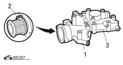
Figure 3.57. Thermostat block outlet pipe with a fitting for draining coolant into the heat exchanger (depending on the vehicle configuration): 1 - nipple; 2 - thermostatic element; 3 - thermostat block
Note: Depending on the engine model, different outlet pipes with a built-in thermostatic element may be installed in the thermostat block (figure 3.56, 3.57). When installing the pipe, make sure that there is a sealing gasket.
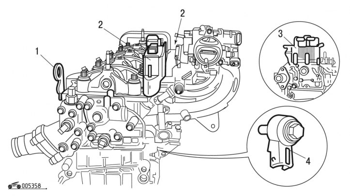
Figure 3.58. Installation of attachments located on the intake manifold side: 1 - lifting eyes for slinging the power unit; 2 - compact ignition coil block (depending on the engine type); 3 - coil housing and ignition coil (depending on the engine type); 4 - knock sensor
86. Install the eyes 1 (figure 3.58) for slinging the power unit.
87. Tighten the lifting eye bolts to a torque of 30 Nm.
88. Install the spark plugs into the holes in the cylinder head.
89. Tighten the spark plugs to 28 N·m.
90. Install the ignition coil assembly.
91. Tighten the ignition coil assembly mounting bolts to 8 N·m.
92. Install the coil housing and ignition coil.
93. Tighten the ignition coil mounting bolts to 5 N·m.
94. Install knock sensor 4 on the cylinder block.
95. Tighten the knock sensor mounting bolt to 2 Nm.
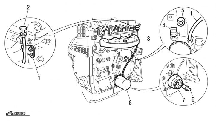
Figure 3.59. Installation of attachments located on the exhaust manifold side: 1 - oil dipstick guide tube; 2 - oil dipstick; 3 - exhaust manifold heat shield; 4 - oil pressure indicator sensor (depending on the vehicle configuration); 5 - oil pressure indicator sensor; 6 - threaded nipple (depending on the configuration); 7 - heat exchanger (depending on the configuration); 8 - oil filter
96. Install heat shield 3 (figure 3.59) exhaust manifold.
97. Tighten the heat shield mounting bolts to 8 Nm.
98. Install the guide tube 1 of the oil dipstick (the tightness of the connection with the cylinder block is ensured by using the RECTIJOINT sealant paste).
99. Insert the oil dipstick into the guide tube.
100. Install the oil pressure indicator sensor.
101. Tighten the sensor to 27 N·m.
102. Install heat exchanger 7 (if it is used on this vehicle) and screw threaded fitting 6 into it. Tighten the threaded fitting to a torque of 8 Nm.
103. Lubricate the sealing ring of the new oil filter 8 with engine oil and install the filter, screwing it manually to the fitting on the cylinder block.
104. Install oil pressure indicator sensor 5.
105. Tighten sensor 5 to 25 Nm.
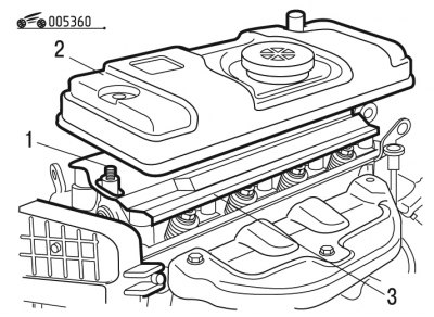
Figure 3.60. Installing the cylinder head cover: 1 - spacer bushings; 2 - cylinder head cover with gasket; 3 - oil deflector screen
106. Install the oil deflector screen 3 (figure 3.60).
107. Install two spacers onto the studs on top of the oil deflector screen.
108. Install the cylinder head cover with a new gasket.
Note: The cylinder head cover is available with 6mm or 8mm diameter mounting holes.
109. For cylinder head cover with 8 mm diameter holes: install new sealing washers under the nuts. Tighten the nuts to 16 N·m.
110. For cylinder head cover with 6 mm diameter holes: tighten the nuts to 7 N·m. The nuts have their own seals, so sealing washers are not placed under them.
Remember that the tightness of the cylinder head cover depends on the thoroughness of all operations during its installation.
111. Turn the crankshaft until the timing marks are aligned. The crankshaft can be turned with a wrench on the bolt temporarily screwed into the front end of the crankshaft.
WarningDo not rotate the crankshaft or camshaft with the cylinder head installed and the piston of any cylinder at top dead center. This will cause the piston to strike the valves and damage the valve train and crank mechanism.
112. Install the tension roller and secure it in the position of minimum belt tension.
113. Put the toothed belt on the crankshaft pulley and, while tensioning both branches of the belt, put the left branch on the coolant pump pulley and put it behind the tension roller. Put the belt on the camshaft pulley and slightly tension it with the tension roller, turning the roller axis counterclockwise. When installing the belt, avoid sharp bends.
114. Turn the crankshaft two revolutions in the direction of rotation and check that the timing marks match. If the marks match, adjust the belt tension as described in subsection "Timing drive". If the marks do not match, loosen the belt tension, remove it from the camshaft pulley, turn the pulley to the required angle, put the belt on, slightly tighten it with the tension roller, turn the crankshaft again two revolutions and check the alignment of the timing marks.
115. Adjust the valve clearances.
116. Assemble the power unit as specified in subsection "Disassembly and assembly of the power unit".