



Removing and installing a timing belt when replacing an existing belt is relatively simple. In this case, before removing the worn belt, its tension is checked, and the new toothed belt is installed in accordance with the marks made and with the tension that the old belt had.
A special case is a broken toothed belt. The timing belt should be replaced at 100,000 km. If this parameter is not met, the belt may break. The consequences can be severe because the valves will hit the pistons. If this happens, then, in addition to replacing the timing belt, it is necessary to remove the cylinder head to check the condition of the valves and pistons.
XU7 engine
In the gear belt workshops, there are corresponding thrust bolts for securing the camshaft and crankshaft from turning, as well as a control and measuring device for checking the tension of the gear belt. In addition, they have pliers for removing the plastic clips that secure the mudguards in the wheel arches.
If the timing belt breaks, we recommend that you immediately tow the car to a workshop. In case of replacing the belt or removing it and then installing it back in place, the procedure is as follows.
1. Place the front of the vehicle on jack stands, on the crankshaft of the engine of which the auxiliary drive belt pulley is installed.
2. Disconnect the negative (-) battery terminal.
3. Remove the wheel.
4. Remove the fender liner in the wheel arch. To do this, remove both fender liner clips and unscrew the mounting bolts (see illustration).
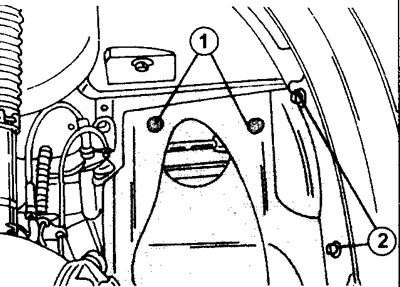
13.4 Remove the fender liner in the wheel arch. To do this, remove both fasteners 1 of the fender liner and unscrew the mounting bolts 2. The illustration only shows two bolts. Three more are located at the bottom of the fender liner
5. Remove the accessory drive belt.
6. Remove the upper part of the timing belt guard.
7. Remove the protective cover under the flywheel (clutch).
8. Place a socket wrench on the timing gear mounting bolt on the crankshaft and rotate the engine in the direction of rotation until the camshaft is positioned as shown in (illustrations 13.8).
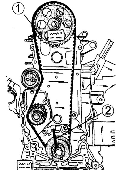
13.8 Engine with installed toothed belt
1 - location of the stop bolt that prevents the camshaft from turning
2 - location of the stop bolt that prevents the crankshaft from turning
In this position, install the thrust bolt (10 mm) into the hole on the camshaft gear and into the corresponding hole on the cylinder head housing. The crankshaft is fixed in the same way. Both stop bolts are different from each other. Do not lock the crankshaft or camshaft with smaller diameter bolts.
9. Secure the crankshaft from turning by installing a brake shoe on the ring gear or inserting a screwdriver and unscrewing the mounting bolt located in the middle of the belt pulley.
10. Remove the belt pulley. If the pulley is tight and does not budge, use a pry bar, alternately pressing the pulley from different sides. If present, remove the pulley using a puller as shown in the illustration.
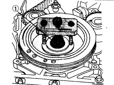
13.10 Remove the belt drive pulley from the crankshaft using a puller
11. Remove the lower part of the timing belt guard. Now you can begin to remove the timing belt itself.
Caution! If the timing belt is removed only for replacement, then in the absence of a belt tensioning device, check the tension of the belt being removed. To do this, squeeze the belt with your thumb and index finger and try to move it to one side and then to the other. Remember or mark the amplitude by which the toothed belt shifts. You can also do it differently. Press the belt with your thumb and measure the amount of deflection using a ruler, selecting the appropriate starting point. Write down the obtained value.
12. Loosen the toothed belt tension roller nut and move the roller to the side to loosen the toothed belt tension and remove it from the gear (see illustration).
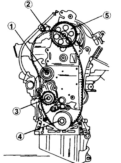
13.12 Loosen the toothed belt tension roller nut and move the roller to the side to loosen the toothed belt tension and remove it from the gear.
1 - timing belt tension roller
2 - toothed belt
3 - water pump gear
4 - crankshaft timing gear
5 - camshaft gear
13. Mark the direction of rotation of the toothed belt. It is most convenient to indicate the direction with an arrow pointing in the direction of belt rotation.
14. Place the removed belt aside so that no oil or grease gets on it during repair work, and also to prevent damage. It is best to hang the belt on a nail, which will prevent it from bending.
If necessary, the camshaft gear, crankshaft gear or tension roller can be replaced. Even if the tension roller is not removed, you need to check its movement to make sure that the roller does not "stick".
Caution! Never turn the camshaft or crankshaft with the timing belt removed, regardless of the type of work being performed.
15. Place the toothed belt on the camshaft and crankshaft gears, as well as on the water pump drive gear and on the tension roller. When installing the belt, follow the following procedure. First, the belt is placed on the camshaft gear. The long side of the belt should be kept taut during installation.
Caution: If the timing belt is installed without securing the camshaft and crankshaft with stop bolts, be careful not to turn the shafts. If the thrust bolts are installed, remove the thrust bolt that secures the crankshaft.
16. Install the belt pulley on the crankshaft. Before this, place a spacer washer on the key and tighten the pulley mounting bolt (see illustration).
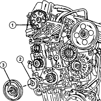
13.16 Install the belt pulley on the crankshaft. Before this, place a spacer washer on the key and tighten the pulley mounting bolt
1 - thrust bolt for fixing the camshaft gear
2 - spacer washer
3 - crankshaft belt pulley
17. Loosen the tension roller and use it to tension the timing belt. Tighten the roller mounting bolt again.
18. Rotate the crankshaft at least two revolutions using a socket head, securing it to the belt pulley bolt, to ensure the timing belt is properly seated. Rotate the crankshaft clockwise when viewed from the front end of the engine. After turning the engine, set the piston of the first cylinder to TDC.
19. Loosen the timing belt tension roller mounting bolt and wait until the timing belt "lies" on the roller and tighten the roller mounting bolt with a torque of 20 Nm.
20. Check the tension of the timing belt and make sure that it matches the tension with which the previous belt was tensioned. The tension of the timing belt can be adjusted using the tension roller. It has two holes into which a trunnion (hook) key can be inserted to turn the roller.
Please note: The information provided above has been tested in practice; however, accurate and correct settings and adjustments can only be achieved with the use of appropriate instruments.
21. Remove the belt pulley from the crankshaft, install the timing belt cover and then install the belt pulley. When performing these operations, hold the crankshaft from turning and tighten the pulley mounting bolt to a torque of 120 Nm.
22. Install all remaining parts.
XU10 engine (with 8 valves)
23. Review the instructions provided for the XU7 engine. The precautions, tools, and equipment required for working on the XU7 engine are also fully applicable to the XUI0 engine. When replacing the timing belt on this engine, follow the procedure below.
24. Place the front of the vehicle on jack stands.
25. Disconnect the ground (-) cable from the battery.
26. Remove the wheel mounting bolts to provide access to the crankshaft.
27. Remove the fender liner in the wheel arch (see illustration I3.4).
28. Remove the V-ribbed belt and the V-ribbed belt tensioner pulley to gain access to other components.
29. Remove the upper part of the timing belt guard (see illustration).
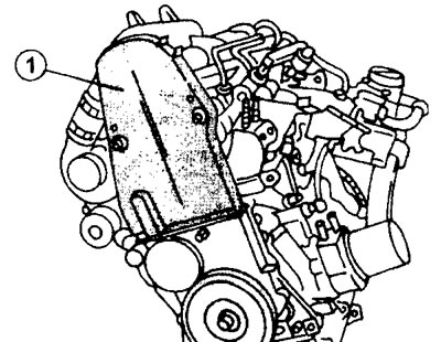
13.29 Remove the upper part 1 of the timing belt guard
30. Turn the crankshaft. by inserting the socket wrench head into the slot of the belt pulley mounting bolt. Rotate the crankshaft until then. until the holes for installing the stop bolts on the toothed belt gears on the crankshaft and camshaft are in the appropriate position. The thrust bolt can be installed into the crankshaft gear when the hole in it is approximately at the 11 o'clock position when the gear is compared with the dial (see illustration).
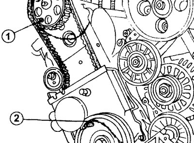
13.30 Installing thrust bolts in the crankshaft and camshaft gears to prevent them from turning
1 - gear and thrust bolt of the camshaft
2 - gear and crankshaft thrust bolt
Caution! Do not turn the crankshaft in the direction opposite to its rotation.
31. Engage the gear to lock the crankshaft and remove the belt pulley mounting bolt on the crankshaft. Never use a stop bolt inserted into a hole on a timing belt sprocket as a counterstop when loosening a belt pulley bolt. You can also prevent the crankshaft from turning using a brake shoe installed on the flywheel ring gear. To do this, you need to remove the flywheel protective cover.
32. Remove the belt pulley from the crankshaft. The crankshaft should not turn during this process. If necessary, you can use a puller (see illustration).
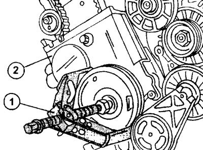
13.32 Removing the belt pulley from the crankshaft using a three-console puller 1
33. Remove the lower part of the timing belt guard. Now you can begin to remove the timing belt itself.
Caution! If the timing belt is being removed only for replacement, and a belt tensioning tool is not available, check the tension of the belt being removed. To do this, squeeze the belt with your thumb and index finger and try to move it to one side and then to the other. Remember or mark the amplitude by which the toothed belt shifts. You can also do it differently. Press the belt with your thumb and measure the amount of deflection using a ruler, selecting the appropriate starting point. Write down the obtained value.
34. Loosen the timing belt tension roller mounting bolt and move the roller to the side, loosening the timing belt tension (see illustration).
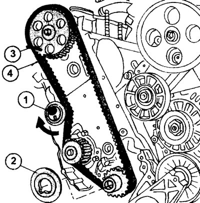
13.34 Loosen bolt 1 securing toothed belt tension roller 4 and move the roller to the side, loosening the toothed belt tension. Also remove the spacer washer from the crankshaft
Remove the timing belt. If the old timing belt is to be reinstalled, the direction of rotation of the belt must be marked.
35. Remove the spacer washer from the crankshaft. Do not remove the thrust bolt from the hole in the camshaft gear.
If necessary, you can also replace the camshaft gear, the timing belt gear on the crankshaft, and the timing belt tension roller. If the tension roller will not be removed, then you need to check its movement to make sure that the roller is not "sticking".
Caution! Never turn the camshaft or crankshaft with the timing belt removed, regardless of the type of work being performed.
36. Place the toothed belt on the camshaft and crankshaft gears, as well as on the water pump drive gear and on the tension roller. When installing the belt, follow the following procedure. First, the belt is placed on the camshaft gear. The long side of the belt should be kept taut during installation.
Caution: If the timing belt is installed without securing the camshaft and crankshaft with stop bolts, be careful not to turn the shafts. If the thrust bolts are installed, remove the thrust bolt that secures the crankshaft.
36. Install the spacer washer onto the crankshaft, then the belt pulley and secure it with the bolt.
37. Turn the timing belt tension roller in the direction as shown in the illustration,
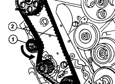
13.37 Turn the tension roller 1 of the toothed belt 2 to slightly tighten the toothed belt
to tighten the timing belt a little. Tighten the roller mounting bolt in this position.
38. Rotate the crankshaft at least two revolutions using a socket head, securing it to the belt pulley bolt, to ensure the timing belt is seated properly. Rotate the crankshaft clockwise when viewed from the front end of the engine. After turning the engine, set the piston of the first cylinder to TDC.
39. Loosen the timing belt tension roller mounting bolt and wait until the timing belt "lies" on the roller and tighten the roller mounting bolt with a torque of 20 Nm.
40. Check the tension of the timing belt and make sure that it matches the tension with which the previous belt was tensioned.
The timing belt tension can be adjusted using the tension roller. It has two holes into which a trunnion (hook) key can be inserted to turn the roller.
Please note: The information provided above has been tested in practice; however, accurate and correct settings and adjustments can only be achieved with the use of appropriate instruments.
41. Remove the belt pulley from the crankshaft, install the timing belt cover and then install the belt pulley. When performing these operations, hold the crankshaft from turning and tighten the pulley mounting bolt to a torque of 110 Nm.
42. Install all remaining parts.
XU10 engine (with 16 valves)
This engine has two camshafts and two timing belt tension rollers located on the right and left sides. The water pump is also driven by a toothed belt. The timing belt must be replaced after every 100,000 kilometers. As with the removal and installation of the timing belt on the previously mentioned engine types, replacing the timing belt on this engine also requires special tools, and only for normal routine timing belt replacement can the procedure described below be followed.
The order of work up to removing the protective cover of the toothed belt is completely identical to the sequence of actions specified for an engine with 8 valves. In addition, it is necessary to remove the front engine mount fastening to provide access to the relevant parts (see illustration 13.0).
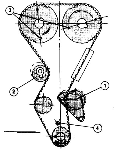
13.0 Timing belt routing on 16-valve engines.
1 - timing belt tension roller
2 - timing belt tension roller
3 - camshaft gear thrust bolts
4 - crankshaft gear thrust bolt
Due to the fact that this type of engine has two camshafts, the removal and installation of the timing belt is significantly more complicated compared to an engine with one camshaft. In this case, the timing belt tension must be achieved using two tension rollers. There are also differences in the fastening of the protective cover of the toothed belt. In addition to the three bolts securing the casing at the top, you need to unscrew the two nuts in its center. And only after this can the upper part of the protective cover be removed.
43. Engage the gear to lock the crankshaft and unscrew the belt pulley mounting bolts on the crankshaft and remove the belt pulley (see illustration)
13.43 Front side of 16 valve engine.
1 - protective cover mounting bolts
2 - protective cover latches
3 - mounting bolts
4 - belt tension roller mounting bolts
5 - bolts for fastening the belt pulley to the crankshaft
6 - bolt securing the timing gear to the crankshaft
7 - bolts for fastening the belt pulley to the crankshaft
44. Remove the V-belt tensioner so that it does not interfere with further work.
45. Remove the lower part of the timing belt guard by unscrewing the four bolts.
46. Turn the crankshaft in the direction of engine rotation by inserting a socket wrench into the slot on the head of the timing gear mounting bolt. Once the thrust bolt mounting holes are in the correct position, insert the thrust bolt into the gear hole on the crankshaft.
47. Insert the thrust bolts into the holes on the gears of both camshafts. When using factory-made bolts, refer to the corresponding bolt markings. The camshaft gear retaining bolts are part number 9041-TZ, and the crankshaft gear retaining bolt is part number 7014 TN. Now you can begin removing the timing belt itself.
Caution! If the timing belt is being removed only for replacement, and a belt tensioning tool is not available, check the tension of the belt being removed. To do this, squeeze the belt with your thumb and index finger and try to move it to one side and then to the other. Remember or mark the amplitude by which the toothed belt shifts. You can also do it differently. Press the belt with your thumb and measure the amount of deflection using a ruler, selecting the appropriate starting point. Take measurements for both sides of the belt. Write down the obtained values.
48. Loosen the bolt securing the left side timing belt tension roller. Move the roller to the side and remove the timing belt (see the left picture in the illustration).
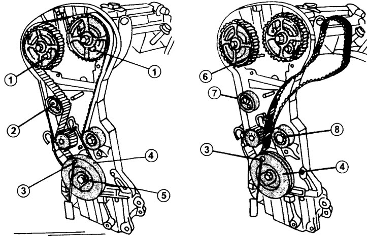
13.48 Removal (left drawing) and installation (right drawing) toothed belt on engines with two camshafts
1 - camshaft gear thrust bolts
2 - timing belt tension roller
3 - crankshaft gear thrust bolt
4 - belt pulley
5 - bolt securing the timing gear to the crankshaft
6 - finger
7 - timing belt tension roller
8 - timing belt tension roller
Remove the timing belt. If the old timing belt is to be reinstalled, the direction of rotation of the belt must be marked.
If necessary, the camshaft gears can also be replaced. the toothed belt gear on the crankshaft, as well as the toothed belt tension rollers.
Caution! Never turn the camshafts or crankshaft with the timing belt removed, regardless of the type of work being performed.
49. Check the movement of the timing belt tension rollers, if they will not be removed or replaced with new ones, and make sure that the rollers have good movement. There should be no traces of grease on the working surface of the rollers.
50. Install the new timing belt as shown in Illustration 13.48 (right drawing). At the bottom, place the belt on the crankshaft timing gear. When installing the old timing belt, do not confuse the direction of its rotation.
51. Install the belt pulley onto the crankshaft and temporarily secure it. Insert the stop bolt 3 into the hole on the pulley (see illustration 13.48).
52. Unscrew bolt 6 (see illustration 13.48).
53. Unscrew the bolts securing the gears of both camshafts. Do not remove the stop bolts from the gear holes, but they cannot be used as stops when unscrewing the bolts securing the gears. In this case, the thrust bolts will simply break. In this case, a thrust shoe is used to secure the gears (see illustration) or a roller, securing it in the gear and on the cylinder head.
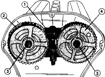
13.53 Camshaft gears.
1 - thrust shoe for holding gears
2 - left camshaft gear
3 - camshaft gear mounting bolts
4 - right camshaft gear
54. Temporarily tighten the bolts 3 securing the gears to the camshafts so that there is no gap left between the gear and the shaft flange, and the gears themselves can be moved freely on the shaft.
55. Place the toothed belt on the water pump drive gear.
56. Place the toothed belt on the right tension roller 8 (see illustration 13.48).
57. Place the toothed belt on the left tension roller 7 (see illustration 13.48).
58. Tighten the right side of the timing belt and place it on the right camshaft gear (see illustration). The bolt securing the gear to the camshaft after the belt is installed is tightened to a torque of 75 Nm.
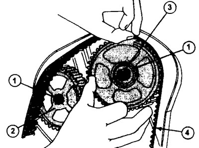
13.58 Tighten the right side of the timing belt and place it on the right camshaft gear.
1 - bolts for fastening the gear on the camshaft
2 - left camshaft drive gear
3 - right camshaft drive gear
4 - toothed belt
59. Place the toothed belt on the second camshaft drive gear (see illustration 13.0)
60. Loosen the fastening of both toothed belt tension rollers and, moving the left roller 7 (see illustration 13.48) to the timing belt, tighten it as it was before removal. Tighten the mounting bolt of this tension roller to a torque of 20 Nm.
61. Turn roller 7 clockwise and tighten the roller mounting bolt again with a torque of 20 Nm if it has loosened while turning the roller. The roller is rotated by means of a journal (hook) a key that is inserted into the holes on the roller.
62. Turn the crankshaft two revolutions in the direction of engine rotation so that the stop bolts can be inserted into the holes of the crankshaft timing gear and both camshaft drive gears.
63. Check the timing belt tension again. It should match the values obtained when removing the timing belt. Otherwise, repeat the timing belt installation.
Please note: The information provided above has been tested in practice; however, accurate and correct settings and adjustments can only be achieved with the use of appropriate instruments and tools.