



Table of contents: Valves 🠇 Valve seats 🠇 Valve springs 🠇 Valve guide bushings 🠇 Cylinder head 🠇 Camshaft 🠇
We do not recommend overhauling the timing mechanism yourself. If, during the inspection of the mechanism, wear or damage to parts is detected, the engine should be delivered to a workshop, which will perform an overhaul.
Valves
Minor damage to the valve head surfaces can be repaired by grinding the valves into the cylinder head seats.
1. Measure the valves and compare the obtained data with the specifications. Replace valves whose wear exceeds the established tolerances with new ones. Pay special attention to the condition of the valve head chamfers and the absence of chamfer burns. Valve head thickness must be at least 0.50 mm. We recommend replacing valves whose head thickness is close to the minimum permissible at the time of inspection. When determining the thickness of the valve head, the thickness of the head chamfer is measured.
If the ends of the valve stems are worn, they can be processed on a grinding machine. It should be taken into account that during the grinding process no more than 0.5 mm of rod material can be removed.
Valve heads can be machined on a special grinding machine for grinding valves, provided that the residual thickness of the valve stems after grinding is at least 0.5 mm.
2. Check the condition of the valve stems and also measure the inner diameter of the valve guides. To do this, you will need a micrometer to measure the inside diameter and a micrometer to measure the outside diameter.
Valve seats
3. Check the condition of the valve seats and ensure there is no wear or pitting. Minor wear defects can be corrected by milling the 45° chamfers. If wear is significant, the valve seats should be re-milled or the seat rings replaced. To replace the rings, it is necessary to drill out the holes for the seats, which is recommended to be done by an engine repair shop.
Valve springs
To properly test valve springs, you need a suitable measuring device to determine the spring length (deformation) under load. In this case, it is best to contact a workshop.
Original is contained on the portal PeugeotBook.ru
Valve guide bushings
If it turns out that the inside of the valve bushings is worn, then it is best to contact an engine repair shop to take the appropriate measurements and, if necessary, replace the bushings. When replacing the guide bushing, it will be necessary to mill the valve seats. This means that almost the entire valve timing mechanism needs to be rebuilt.
Cylinder head
4. Clean the mating surfaces of the cylinder head and cylinder block and ensure that the head is not warped. To do this, install a measuring ruler on the cylinder head and, using a template, measure the gap between the ruler and the surface of the cylinder head in the longitudinal, transverse and diagonal directions. If a template with a thickness greater than 0.05 mm can be inserted into the gap, then grinding of the head is necessary. If the gap is greater than the specified size in at least one place, the cylinder head should be replaced with a new one. Cylinder head modifications can be performed if the adjustment requires removing no more than 0.02 mm of metal. We also recommend entrusting this work to a workshop (see illustration).
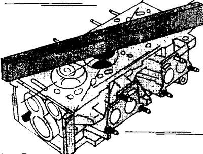
7.4 Check the cylinder head surface for warpage. The arrows show the directions of measurements using the template
Camshaft
As mentioned, the camshaft(s) are not universal. This must be taken into account when replacing the camshaft, and when ordering a new shaft, indicate the engine type, year of engine production, as well as the power in hp or kW.
8. Check the condition of the shaft journals and ensure there is no damage. If the journals are damaged, we recommend replacing the camshaft and cylinder head rather than repairing or overhauling them.
9. Install the camshaft for measuring axial play into the cylinder head and secure it with a thrust plate. Place the cylinder head on a flat surface (see illustration).
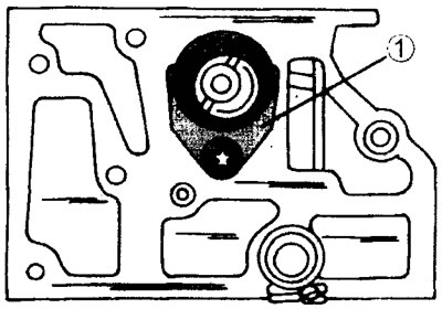
7.9 Fastening the camshaft in the cylinder head
1 - thrust plate. Fastened with a socket head bolt
10. Attach a pointer-type indicator to the end of the shaft and move the camshaft back and forth in the axial direction. If the clearance exceeds 0.16 mm, the thrust plate is worn out and must be replaced. In the worst case, wear of the camshaft flange, which is fixed between the cylinder head, is possible (with bearing housing) and the auxiliary units housing.