



Table of contents: XU10 engines 🠇 XU7 1.8-liter engines 🠇
The dismantled engine can be completely disassembled. The engine disassembly procedure is as follows (don't forget the difference between an 8-valve engine and a 16-valve engine).
XU10 engines
1. Drain the engine oil.
2. Disconnect all parts attached to the cylinder head.
3. Secure the flywheel from turning. To do this, install the appropriate shoe on the flywheel ring gear or insert a large screwdriver (see illustration).
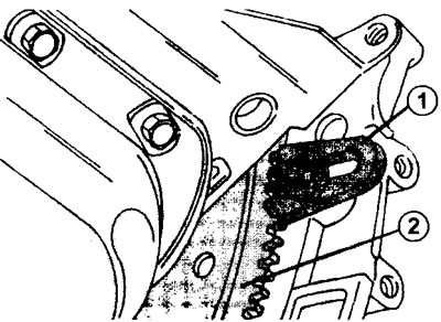
4.3 Flywheel 2 is locked from turning by a corresponding "brake shoe" 1, which is attached to the gear ring
4. Unscrew the mounting bolt with gasket on the inner side of the crankshaft belt pulley.
5. Remove the belt pulley from the shaft. Use pry bars if necessary.
6. Remove the two-piece timing belt guard, oil level indicator (dipstick) guide tube, coolant inlet pipe and outlet manifold (see illustration)
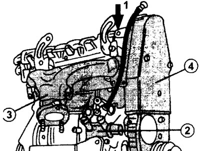
4.6 Remove the two-piece protective cover 4 of the toothed belt, the guide tube 1 of the oil level indicator (dipstick), the inlet pipe 2 of the coolant and the outlet manifold 3
7. Remove the oil filter using a filter wrench. If there is none, pierce the oil filter with a screwdriver and disconnect it by turning the screwdriver. The oil filter must be replaced in any case, so damage to it during removal does not matter.
8. Loosen the mounting bolts on the clutch pressure plate flywheel in a crosswise pattern. Before removing the pressure plate, mark the position of the plate and flywheel relative to each other so that they can be installed in the same way during assembly (see illustration).
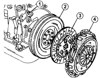
4.8 Removing the clutch pressure plate
1 - flywheel brake shoe
2 - flywheel
3 - driven clutch disc
4 - clutch pressure plate
9. Remove the central bolt of the camshaft gear, holding it from turning. To prevent the gear from turning, you can use a drill of the appropriate diameter (see illustration).
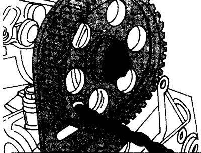
4.9 To prevent the gear from turning, you can use a drill of the appropriate diameter
The position of the crankshaft and camshaft is not important in this case, because the valve timing mechanism will still need to be adjusted during engine assembly.
10. Remove the toothed belt from the gears and tension roller. To do this, loosen the belt tensioner, move the tensioner to the side and remove the toothed belt from the gears (see illustration).
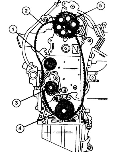
4.10 Removing the timing belt. Engine HSHO
1 - tension roller
2 - toothed belt
3 - water pump gear
4 - crankshaft timing gear
5 - camshaft drive gear
11. Mark the direction of rotation of the timing belt with paint or a marker. It coincides with the direction of rotation of the engine. This mark will be needed if the old timing belt is to be installed.
Caution: Do not allow the timing belt to come into contact with oil or grease, and avoid bending the belt. It is recommended to hang the removed timing belt on a hook or nail.
The camshaft drive gear does not need to be removed.
12. Disconnect the spark plug high-voltage wires.
13. Unscrew the mounting bolts and remove the cylinder head cover. For engines with 16 valves (two camshafts) the cylinder head cover mounting bolts are unscrewed in several passes, working from the center outward. For 8-valve engines, the cylinder head cover is secured as shown in (illustrations 4.13).
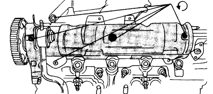
4.13 Fastening the cylinder head cover of an 8-valve engine
14. Disconnect and remove the generator together with the mounting console, oil pressure regulator and engine mount brackets.
15. Loosen the eight flywheel mounting bolts in a cross pattern and knock off the flywheel with a rubber hammer. Be careful not to drop the flywheel. There is a small plate above the flywheel that can also be removed. At the same time, access to the threaded plug of the oil hole will be freed. Unscrew the plug using a socket wrench.
16. Remove the crankshaft timing gear. Behind the gear there is an insert and a toothed belt guide, which are removed together with the gear. Next to the water pump drive gear there is a second oil drain hole, closed with a screw plug. Unscrew this plug as well using a socket wrench.
17. Remove the cover on the end side of the engine, secured with six bolts. Knock out the seal located in the cover (see illustration).
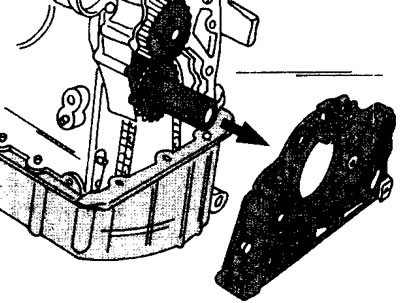
4.17 Remove the cover on the end side of the engine
18. Loosen the timing belt tension roller mounting bolt and remove the roller. The support bolt can also be unscrewed.
19. Remove the water pump mounting bolts, which can be accessed after removing the cover from the end side of the engine. At the same time, remove the nearby coolant hose and gasket by unscrewing the three mounting bolts.
20. Remove the remaining engine mount brackets.
21. Unscrew the mounting bolts and remove the cylinder head (see the relevant chapter). After removing the cylinder head, record the corresponding cylinder numbers on the top of the pistons.
22. Turn the engine over with the crankcase facing up and remove the crankcase. The crankcase of this type of engine can be installed either with or without a gasket.
23. Unscrew the three oil pump mounting bolts on the bottom of the cylinder block and remove the oil pump. To remove the oil pump, you must first lift it and then move it forward. The pump drive gear is removed together with the chain. Typically, a gasket is installed between the oil pump and the cylinder block (see illustration).
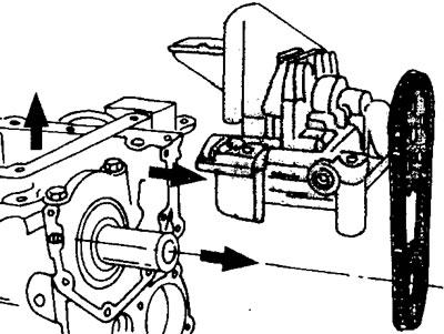
4.23 In order to remove the oil pump, it must first be lifted and then moved forward (see arrows)
24. Unscrew the nuts of the connecting rod bearing cap bolts in order and remove the caps. To remove the connecting rod bearings, the crankshaft must be turned so that the corresponding bearings, two at a time, come out to the bottom dead center. Remove the bearing shells from the crankpins and install them in the corresponding caps. The connecting rods and connecting rod caps have a mark on one side.
25. Knock the pistons together with the connecting rods out of the piston holes. Before doing this, make sure that the pistons are marked according to the cylinder numbering. After removing the piston and connecting rod, secure the connecting rod cap and bearing to the connecting rod.
26. Use a punch to make marks on the main bearing caps and on the cylinder block.
27. Loosen the bolts, working from the outside towards the middle, and remove the covers together with the lower liners. When removing the second cover, remove the two thrust half rings (see illustration).
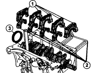
4.27 Remove the main bearing caps 1, the connecting rod caps 2 and the oil seal on the rear end of the crankshaft
When purchasing main bearing shells, be sure to indicate the year of manufacture and engine number, as the shells may differ.
28. Remove the crankshaft and upper main bearing shells and the two remaining thrust half rings.
29. Assemble the liners and lids together. The oil seal on the rear end of the crankshaft can be removed after removing the shaft from the cylinder block (see illustration 4.27).
XU7 1.8-liter engines
Disassembly of this engine, including removal of the cylinder head, is performed identically.
30. Remove the cylinder head (see the relevant chapter).
31. Mark the pistons and cylinder liners with a marker.
32. Loosen the nuts of the connecting rod cap bolts and remove the caps, as well as the cylinder liners together with the pistons and connecting rods and place them in the appropriate place. Remove the pistons from the cylinder liners.
33. Remove the main bearing caps with the lower liners, having first marked the mounting position of the caps on the cylinder block.
34. Remove the crankshaft and take the upper halves of the bearings out of the beds.