
2. Remove the brake booster vacuum pump (see chapter 8).
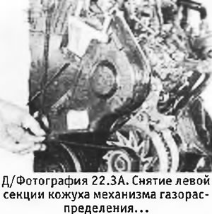
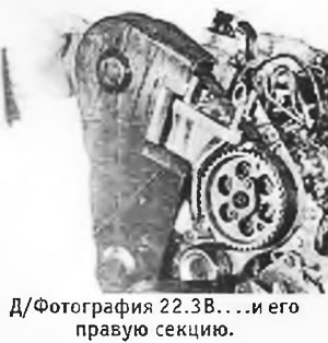
3. Pull up the special clip, loosen the spring clips and remove the two sections of the casing of the timing mechanism (see pictures).
 |  |
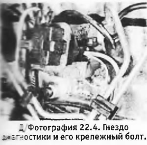
4. Unscrew the bolt and remove the diagnostic socket together with this bracket (if available) (see photo).
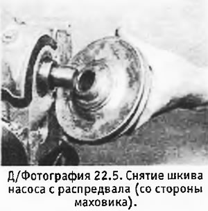
5. Unscrew the bolt and remove the pump pulley from the end of the camshaft (flywheel side) (see photo). If it is rusted, you can use a puller. Remove the segment key.
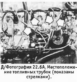
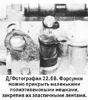
6. Remember the position of the fuel pipes connecting the injection pump with the nozzles, unscrew the union nuts and remove the pipes. Plug the open ends of the pipes and holes in the injectors and injection pump so that dirt does not get inside. Instead of corks, you can use small plastic bags, securing them with elastic bands (see pictures).
 |  |
7. Disconnect the bypass hoses from the injectors.
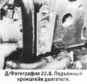
8. Remove the bolts and remove the engine lifting bracket from the cylinder head (see photo).
9. Remove generator (see chapter 10) and its support bracket.
10. Unscrew the oil filter, if necessary using a belt wrench.
11. On a 1.9 liter engine, disconnect the hoses from the oil cooler (where installed). Unscrew the center pin and remove the radiator from the cylinder block. Disconnect the oil cooler hoses from the engine.
12. If not already done, disconnect the bottom hose from the water pump inlet.
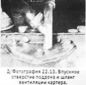
13. Disconnect crankcase ventilation hoses from valve cover and sump inlet (see photo). Remove the clip and pull the oil separator out of the dipstick tube.
14. Remove the oil filler plug with the ventilation hose (if provided).
15. Remove the bolts and remove the intake manifold from the cylinder head (laying is not provided).
16. Unscrew the nuts and remove the exhaust manifold with gaskets from the studs.
17. Loosen the bolt and remove the clamp from the end of the fast idle cable. Loosen the lock nut and remove the outer fast idle cable from the bracket on the injection pump.
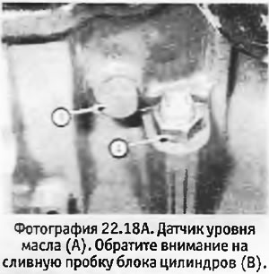
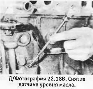
18. Unscrew the oil level sensor (if provided) and remove it from the cylinder block (see photo).
 |  |
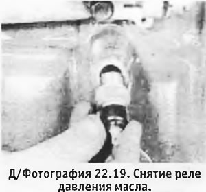
19. Unscrew and remove the oil pressure switch (see photo).
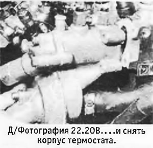
20. Remove the bolts and remove the thermostat housing from the cylinder head along with the fast idle thermoblock and temperature sensor (sensors) (see pictures).
 |  |
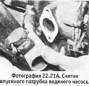
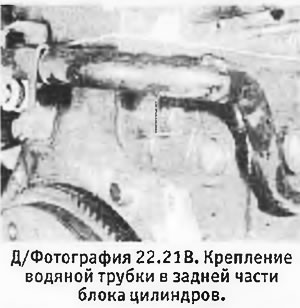
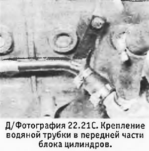
21. To turn out bolts and to remove an inlet branch pipe of the water pump with a lining. Remove the bolt securing the water pipe to the cylinder block (see pictures).
 |  |
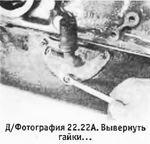
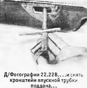
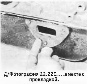
22. Where applicable, remove the nuts securing the inlet tube-sump bracket. Remove bracket with gasket (see pictures).
 |  |
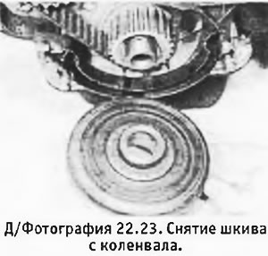
23. Ask an assistant to hold the flywheel motionless with a screwdriver or a metal bar inserted between the teeth of the starter crown and the gearbox guide pin, and unscrew the crankshaft pulley bolt. Remove pulley from crankshaft (see photo).
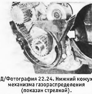
24. Remove the bolts securing the lower casing of the gas distribution mechanism (see photo).
25. Rotate the engine with the flywheel so that the three bolt holes in the camshaft sprockets and injection pump align with the corresponding holes in the engine front plate.
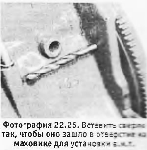
26. Insert a metal bar with a diameter of 8.5 mm into a special hole on the left end flange of the 6 cylinder block (next to the starter). Carefully turn the engine in either direction so that the bar enters the hole on the flywheel for installing the TDC. (see photo).
27. Insert 3 M8 bolts into the holes on the camshaft sprockets to the injection pump and manually screw them into the engine front plate.
28. Loosen the pivot nut and adjusting bolt of the timing belt tensioner and turn the bracket counterclockwise to release tension from the timing belt. Tighten the adjusting bolt again to compensate for the tensioner in this position.
29. Put an arrow on the timing belt to show its normal direction of movement, and remove it from the camshaft sprockets, injection pump, water pump and crankshaft.
30. Remove the bolts and remove the valve cover. Remove gasket.
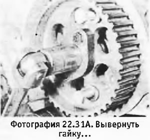
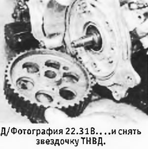
31. Having fixed the injection pump sprocket with the help of the gas distributor housing bolts, return the central nut that secures the sprocket to the end of the pump shaft. Screw in the bolts and remove the pump sprocket together with the nut. Remove segments key (if she falls). To remove the sprocket, you will need a puller, which is attached to it using a plate bolted over the nut and resting on a special outer shoulder on the nut.
 |  |
32. Similarly, unscrew the central bolt of the camshaft sprocket and remove it.
33. Remove the sprocket from the crankshaft. Remove segment key (if she falls).
34. To turn out bolts and to remove the water pump from the block of cylinders. Remove pump gasket.
35. Mark the position of the injection pump relative to its support bracket. Loosen nuts and bolt and remove injection pump.
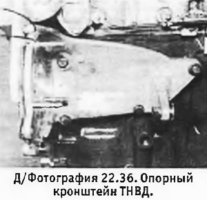
36. Unscrew the bolts and remove the pump support bracket (see photo).
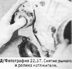
37. Unscrew the adjusting bolt and pivot nut of the timing belt tensioner. While removing the tensioner pulley and arm, you may need a tool to hold the tensioner plunger in place (see section 5). If there is no such tool, the plunger can simply be held by hand (see photo).
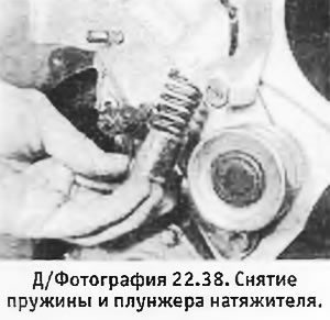
38. Pull out the plunger with the spring (see photo).
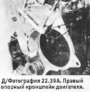
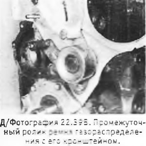
39. Unscrew the bolts and remove the engine support bracket and the timing belt intermediate roller with its bracket (see pictures).
 |  |
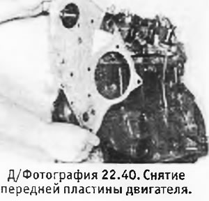
40. Remove the bolts securing the engine front plate (see photo).
41. Gradually unscrew the cylinder head bolts in the reverse order of their tightening (see d/fig. 1.9). Remove bolts with washers.
42. Rock the cylinder head and remove it from the dowel pin on the cylinder block. Remove head gasket.
43. Remove the clutch. While holding the engine from rotation with a screwdriver inserted between the teeth of the starter ring and the gear dowel pin, unscrew the bolts and remove the flywheel from the crankshaft.
44. Turn the engine over and unscrew the pan mounting bolts. Remove the pan and its gasket.
45. Remove the 3 bolts securing the oil pump to the crankcase. Remember how the bolts stood, because. they all have different lengths.
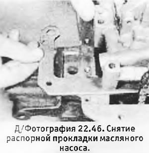
46. Pull out the spacer in the form of a corner from under the oil pump (see photo).
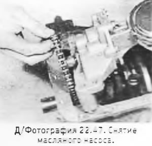
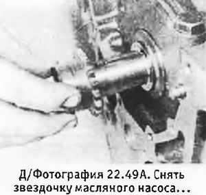
47. Remove the dowel pin and disconnect the oil pump sprocket from the chain. Remove oil pump (see photo).
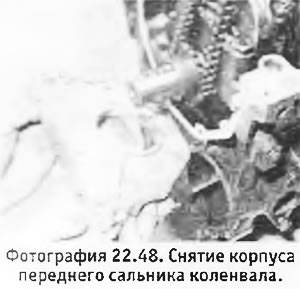
48. Unscrew the bolts and remove the front oil seal housing (see photo). Remove gasket.
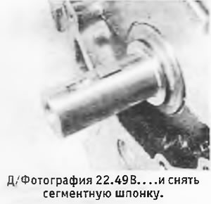
49. Remove the oil pump chain and then its sprocket. Remove segment key (if she falls).
 |  |
50. Check that all connecting rods and connecting rod caps are marked according to their position. If there are no marks, make them yourself (from the oil filter), starting from the flywheel.
51. Install the cylinder block either on its side or on the end where the flywheel was.
52. Turn the crankshaft so that the pistons NN 1 and 4 are in the n.m.t. position. Remove the nuts from the connecting rod cap No. 1, remove the cap and pull out the lower shell of the connecting rod bearing.
53. Use the handle to push the piston out of the cylinder. Temporarily install the connecting rod bearings and cap in place so as not to confuse them later.
54. In the same way, remove the piston N 46, and then turn the crankshaft 180°so that the pistons NN 2 and 3 are in the n.m.t. position. Remove those pistons.
55. The main caps should be numbered 1 to 5 starting from the flywheel. If there are no such numbers, they must be applied independently. Also pay attention to the installation depth of the rear crankshaft oil seal.
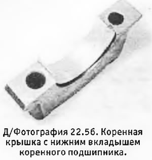
56. Turn over the engine, unscrew the bolts and remove the main covers. Pull out the lower halves of the main bearing shells and spread them over their covers (see photo). Remove thrust washers.
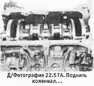
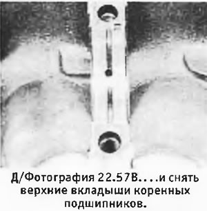
57. Pull out the crankshaft. Remove the old seal and discard it. Remove the upper main bearing shells and arrange them on their covers (pre-marking them so as not to be confused with the lower) (see pictures). Remove and mark the upper thrust washers.
 |  |