
2. Wipe off the protective grease from the new bearings and install the upper bearings (have an oil groove) into their nests on the block. Check that the mounting tabs on the bushings fit into the corresponding slots on the sockets.
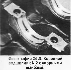
3. Install thrust washers on both sides of bearing N 2 (grooved surfaces) and fix them in place with a little grease (see photo).
4. Lubricate the upper bearing shells and lower the crankshaft into place.
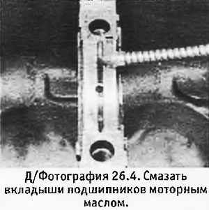
5. Install the lower bearing shells (without oil groove) into their covers, making sure that the mounting tabs fit into the grooves intended for them. Lubricate the bushings with oil.
6. Fit thrust washers on either side of cover #2 and lock them in place with a little grease.
7. Before installing the covers in place, check the axial movement of the crankshaft using a dial gauge mounted on the toe of the crankshaft.
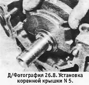
8. Replace covers NN 2-5 (see photo) and check that the mounting tabs of the lower and upper bushings are on the same side. Insert the bolts, but do not tighten them yet.
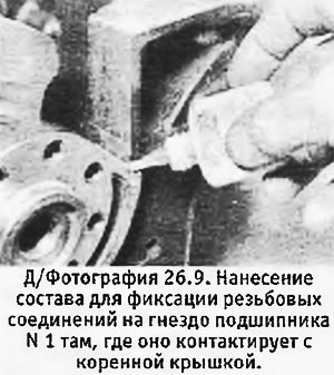
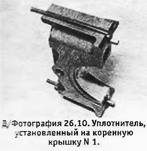
9. Apply some thread locking compound to the contact surface of the N 1 bearing seat on the block (contact surface in root cap N 1) at the places of installation of the seal (see photo).
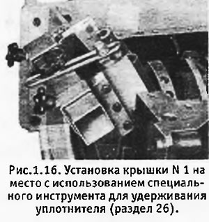
10. Press the seal into the grooves on both sides of the root cover No. 1 (see photo). Prepare 2 metal strips with a thickness of no more than 0.25 mm so that the seal does not move when the cover is installed. In workshops "Peugeot" a special tool is used for this (see d/fig. 1.16), which plays the role of a clamp, however, instead of it, it is quite possible to use metal strips, provided that all burrs that could damage the seal are first removed from them.
 |  |
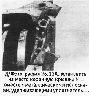
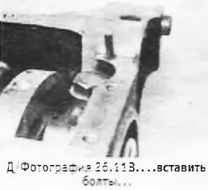
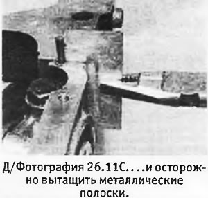
11. Lubricate both sides of the strips with engine oil and, holding them on the seal, reinstall the root cover N 1. Insert the bolts (just don't tighten them) and carefully pull out the strips in a horizontal position using pliers (see pictures).
 |  |
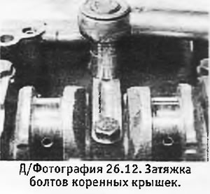
12. Tighten the main cap bolts evenly to the correct torque (see photo).
13. Check the crankshaft for freedom of rotation.
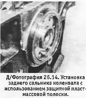
14. Dip a new crankshaft rear oil seal in clean engine oil and install it on the crankshaft with the open end inward and press it without distortion to the original depth using a metal tube slightly less than 102 mm. In order not to damage the gland, you can use a thin plastic strip (see photo). Check that the outer lip of the stuffing box is not bent inward and, if necessary, straighten it with a bent wire.
15. Install the cylinder block on its side or at the end where the flywheel should be.
16. Lay out the assembled connecting rod and piston groups in order together with connecting rod bearings, caps and nuts.
17. Check that the piston ring locks are 180°apart from each other.
18. Clean the connecting rods, connecting rod bearings and caps and press the bearings into place so that the mounting tabs fit into their grooves.
19. Lubricate cylinders, pistons, connecting rod journals and liners with clean engine oil. Install the tool for compressing the piston rings on piston No. 1. With connecting rod journals Nos. Insert the No. 1 piston into the cylinder closest to the flywheel, making sure that the cloverleaf cutout in the bottom is on the oil filter side.
20. Use a hammer handle to push the piston through the piston ring compressor into the cylinder. Bring the connecting rod to the neck and install the connecting rod cap together with the connecting rod bearing shells. Check that the cover is in the correct position.
21. Install the nuts and tighten them to the correct torque. Rotate the crankshaft and check for freedom of rotation.
22. Repeat the above procedure for the remaining three pistons.
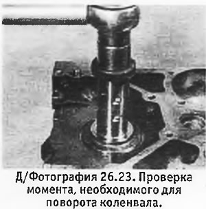
23. Temporarily install the pulley bolt on the crankshaft toe and then use a torque wrench to check that the torque required to turn the crankshaft does not exceed 41 Nm (see photo). At a greater moment, it is necessary to identify and eliminate the cause.
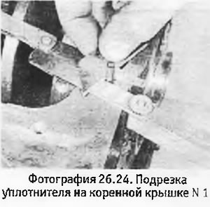
24. Using feeler gauges and a knife, cut the seal on the No. 1 main bearing cap so that it protrudes 1.0 mm above the surface that borders the pan gasket (see photo).
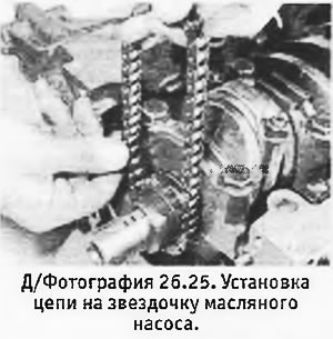
25. Install the keyway into the groove on the crankshaft. Install the oil pump sprocket with the teeth side in. Put the chain on the sprocket and tie its free end to the side so that the chain does not come off (see photo).
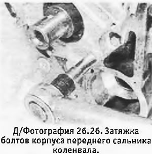
26. Pull the old front oil seal out of the housing. Check that the 2 dowel pins are on the front surface of the cylinder block and reinstall the front oil seal housing with a new gasket. Tighten the body mounting bolts evenly to the correct torque (see photo).
27. To check up, that in the lower part of the block of cylinders there was an adjusting pin. Place the chain on the oil pump sprocket and insert an angle spacer under the pump, making sure that its open end is seated on the pin.
28. Insert the oil pump bolts into their original positions (the longest bolt should go through the pin and the next longest bolt should be next to the oil return hole. Tighten the bolts evenly to the correct torque.
29. Dip a new front oil seal into the engine oil and press it into the housing so that it is flush with the outer surface of the housing.
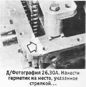
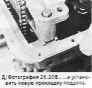
30. Apply some sealant where the front oil seal housing meets the cylinder block (on both sides). Install a new gasket on the block and then the pallet (see pictures). Insert bolts (the correct location of the bolts is shown in D / fig. 1.17) and evenly tighten them to the desired torque. Remove the sump drain plug, replace the washer, reinstall the plug and tighten it.
 |  |
31. Install the flywheel on the crankshaft pin.
32. Apply thread locking fluid to the bolt threads, insert them and tighten to the desired torque, holding the flywheel from rotation with a screwdriver inserted between the teeth of the starter crown and the gearbox locating pin.
33. Turn the cylinder block upside down and reinstall it on the work table.
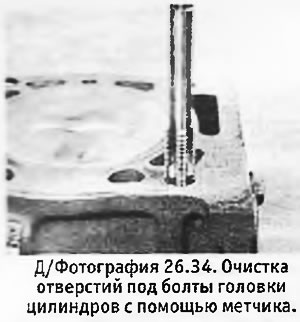
34. Using a tap M12x1.5, check that the holes for the cylinder head bolts are clean (see photo).
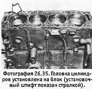
35. Install the cylinder head gasket on the block so that the identification notches or holes are on the flywheel side. Check that the dowel pin is in place (see photo).
36. Turn the crankshaft clockwise (viewed from the timing belt side) so that pistons NN 1 and 4 pass the n.m.t. and reached the middle of their cylinders in the lifting phase. In this case, the pistons NN 2 and 3 will also stand in the middle of their cylinders, but in the lowering phase. The segment key on the toe of the crankshaft must take a position corresponding to the position of the number "9" on the watch face.
37. Check that the camshaft is in the top dead position, in which the segment key looks up, and the protrusions of the cams NN 4 and 6 rest on the pushers.
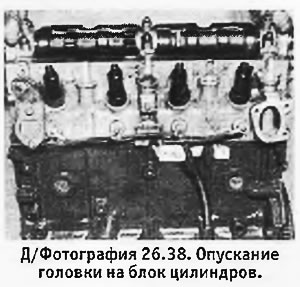
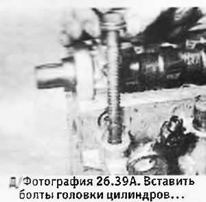
38. Lower the cylinder head onto the block (see photo).
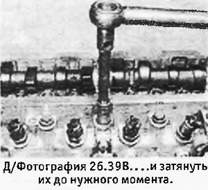
39. Insert cylinder head bolts with washers. Tighten the bolts in the sequence shown in D / fig. 1.ZA or D / fig. 1.9V, in the three steps indicated in Specifications (see pictures).
 |  |
40. Check the valve clearances again and adjust if necessary. This should be done even if the clearances have already been adjusted on the removed head, as clearances may change after installation.
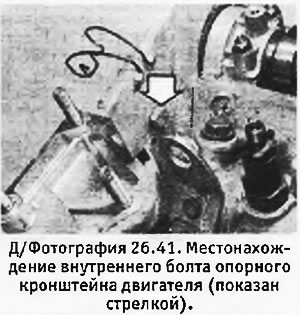
41. Install the engine front plate, then the idler and timing belt bracket and engine support bracket. Tighten all bolts. (Don't forget that support bracket bolt that's on the inside of the engine's front plastic®) (see photo).
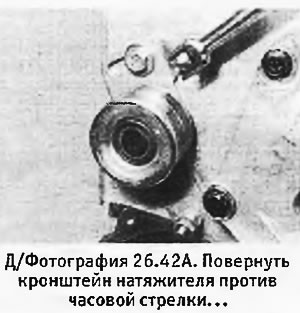
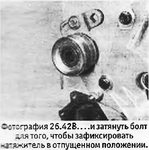
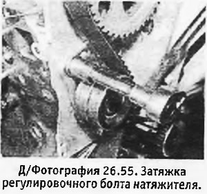
42. Insert the timing belt tensioner spring and plunger into the support bracket. Press the tensioner lever against the plunger and install the bracket with the roller on the pivot pin. Alternatively, the plunger can be compressed using the tool described in Section 5. Install the adjusting bolt and pivot nut and tighten the bolt with the tensioner in the released position (those. with compressed spring) (see pictures).
 |  |
43. Install the injection pump support bracket and tighten its mounting bolts.
44. Install the high-pressure fuel pump, aligning the marks made during its removal. Install and tighten the nuts and then the bolt.
45. Install the water pump with a new gasket and tighten its bolts to the desired torque (see chapter 2).
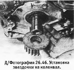
46. Install the segment key in the groove intended for it. Install the timing belt sprocket to the crankshaft (see photo).
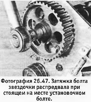
47. Install the sprocket on the camshaft. Apply threadlocker to the threads of the sprocket bolt, insert and tighten to the correct torque while holding the sprocket from rotating. To fix the sprocket, you can use a tool consisting of a metal strip and 2 bolts, or fix the sprocket with a bolt screwed into the cylinder head (see photo).
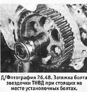
48. Unscrew the bolts securing the special puller to the injection pump sprocket. Install the segment key in place and put the sprocket on the injection pump shaft. Install the nut and tighten it while holding the sprocket using one of the methods described in paragraph 47 (see photo).
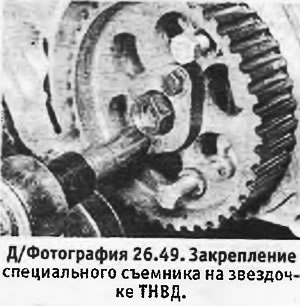
49. Install a special puller on the sprocket and insert and tighten the bolts (see photo).
50. Install the valve cover with a new gasket and tighten its mounting bolts.
51. Check that the camshaft sprockets and injection pump are in the top dead center position. and three set bolts were inserted into the engine front plate.
52. Insert a metal bar with a diameter of 8 mm into a special hole in the left rear flange of the cylinder block and carefully turn the engine clockwise (viewed from the timing belt side) so that the bar goes into the hole in the flywheel for installing the T.M.T. The crankshaft must only be rotated 1/4 turn, as pistons NN 1 and 4 are already in the middle of their stroke in the cylinders. Do not turn the crankshaft more than necessary, because. in this case pistons NN 2 and 3 may hit valves 4 and 6.
53. Put the timing belt on the crankshaft sprocket, checking (in case of old belt), so that the arrow marked on the belt is pointing in the correct direction.
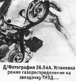
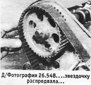
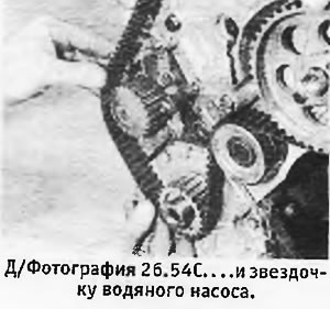
54. Holding the belt so that it does not come off the crankshaft sprocket, put it on the roller and on the sprockets of the injection pump, camshaft and water pump, as well as on the tensioner roller. In order for the belt to fit correctly, it should be installed on the injection pump sprocket only half the width, then put on the camshaft sprocket, making sure that it is still tensioned, and install it completely on the crankshaft sprocket (see pictures). After making sure that the belt is correctly positioned, fully push it onto all the sprockets.
 |  |
55. With the pivot nut loose, loosen the tensioner adjusting bolt while holding the bracket against spring pressure. Slowly release the bracket so that the roller is pressed against the timing belt. Tighten the adjusting bolt again (see photo).
56. Remove the bolts from the camshaft sprockets and injection pump. Pull the metal bar out of the cylinder block.
57. Rotate the engine 2 full turns in the normal direction of rotation. Do not rotate the motor in the reverse direction as the timing belt must be tensioned on the sprockets of the crankshaft of the injection pump and the camshaft.
58. Loosen the tensioner adjusting bolt so that the tensioner spring can press the roller against the timing belt, and then tighten both the adjusting bolt and nut.
59. Check the valve timing by turning the engine so that the holes in the sprockets for the bolts are aligned. Insert a metal bar and check that it goes into the hole in the flywheel.
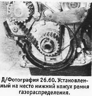
60. Install the lower timing belt cover and tighten its mounting bolts (see photo).
61. Install the pulley on the front end of the crankshaft (per segment strip).
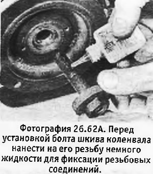
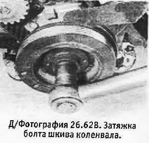
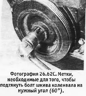
62. Apply threadlocker to the threads of the pulley bolt, insert and tighten to the correct torque. While tightening the bolt, have an assistant hold the flywheel from rotating with a screwdriver inserted between the teeth of the starter ring and the gearbox locating pin. Note that after tightening to initial torque, the bolt must be tightened an additional 60° (one chamfer on the head of the bolt). As an option, before angular tightening, you can mark the edges of the bolt head on the wrench head and the initial position of the bolt head on the pulley.
 |  |
63. Where applicable, install a new gasket on the side of the sump, reinstall the intake tube bracket and tighten the nuts.
64. Install the water pump inlet with a new gasket and tighten the mounting bolts.
65. Bolt the water pipe to the cylinder block and install the hoses.
66. Install the thermostat housing with a new gasket and tighten the mounting bolts.
67. Install the oil pressure switch on the cylinder block and tighten it.
68. Where applicable, replace the oil level sensor and tighten it.
69. Connect the fast idle cable to the injection pump (see chapter 3).
70. Install the exhaust manifold with new gaskets and evenly tighten the fixing nuts.
71. Install the intake manifold and evenly tighten the fixing bolts. The intake manifold is installed without a gasket.
72. Install the oil filler plug with the ventilation hose (if provided).
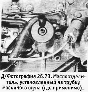
73. Put an oil separator on the dipstick tube (see photo) and secure it with a clamp. Connect the crankcase ventilation hoses to the sump valve and intake pipe.
74. Connect the bottom hose to the water pump inlet.
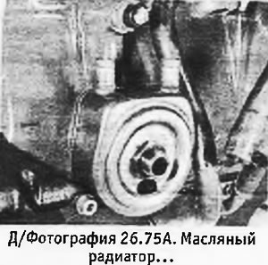
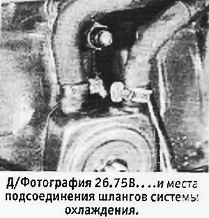
75. On 1.9 liter engines, connect the oil cooler hoses (if available) and install the oil cooler by tightening its central stud to the desired torque (see pictures).
 |  |
76. Apply some engine oil to the oil filter o-ring, install the filter and tighten it by hand.
77. Install generator (see chapter 10).
78. Install the engine lifting bracket on the cylinder head.
79. Connect the bypass hoses to the nozzles.
80. Connect the fuel pipes to the injectors and injection pump and tighten the union nuts to the required torque (see chapter 3).
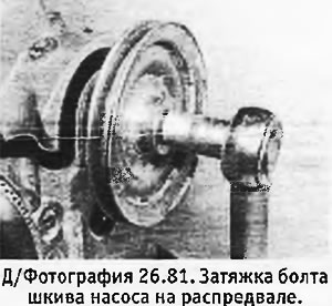
81. Put the pump pulley on the end of the camshaft on the flywheel side. Insert the bolt and tighten it to the correct torque (see photo).
82. Where applicable, install the diagnostic socket with bracket and tighten the mounting bolt.
83. Install 2 sections of the timing belt cover and press the special fixing clip into place.
84. Install the brake booster vacuum pump (see chapter 8).
85. Install the clutch.