
2. Lock the cover in the up position.
3. Engage the handbrake and jack up and support the front of the machine so that there is at least 60 cm between the bumper and the ground. Remove both front wheels.
4. Drain the liquid from the cooling system.
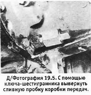
5. Using a hex wrench, unscrew the drain plug and drain the oil from the gearbox into a suitable container (see photo). When finished, reinstall and tighten the drain plug.
6. If necessary, drain the oil from the engine.
7. Remove the air cleaner (see chapter 3).
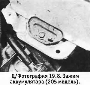
8. Disconnect the wires from the battery, unscrew the clamping bolt and remove the battery and its platform (see photo).
9. Remove the radiator (see chapter 2).
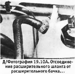
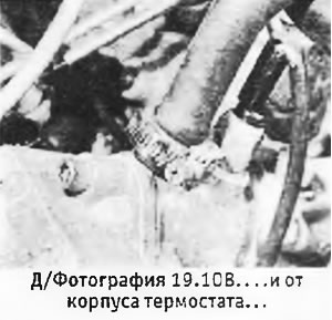
10. Disconnect the upper hose from the thermostat housing and the expansion hose (hoses) - from expansion tank and thermostat housing (see pictures).
 |  |
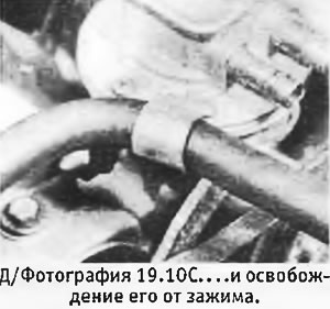
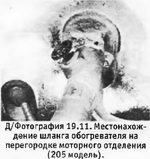
11. Disconnect the heater hoses from the bulkhead of the engine compartment.
12. Where applicable, remove the power steering pump without disconnecting the hoses from it and place it to the side.
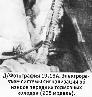
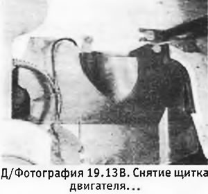
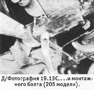
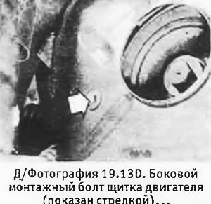
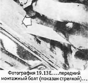
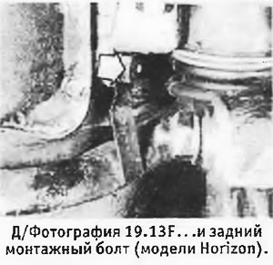
13. Working under the right wheel arch, remove the engine shield. Where applicable, disconnect the front brake pad wear sensor wiring (see pictures).
 |  |
 |  |
 |  |
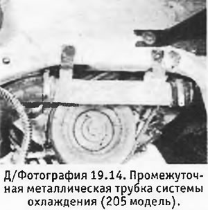
14. Disconnect the lower hoses from the cylinder block, remove the metal tube (if available) from the inner surface of the right wing (see pictures).
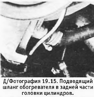
15. Disconnect the heater supply hose from the rear surface of the cylinder head (see photo).
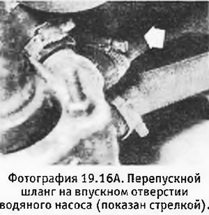
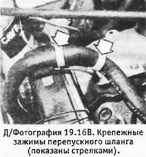
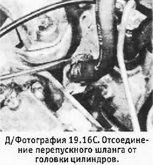
16. Disconnect the bypass hose from the water pump inlet and the front surface of the cylinder head (see pictures).
 |  |
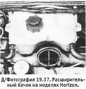
17. Unscrew the bolts and remove the expansion tank in order to provide more space for work.
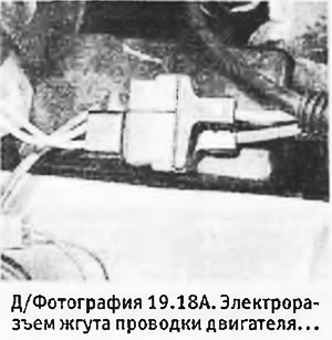
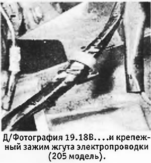
18. Disconnect the engine wiring harness near the battery and remove the harness retaining clip on the transmission (see pictures).
 |  |
19. Disconnect wiring from the following equipment:
- A. starter
- b. generator
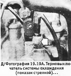
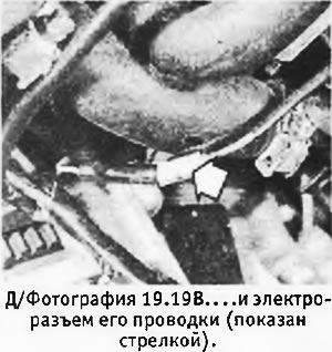
- V. cooling system thermal switch (see pictures)
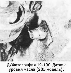
- d. oil level sensor (see photo)
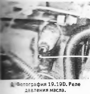
- e. oil pressure switch (see photo)
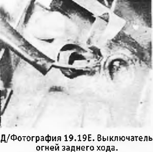
- e. reversing light switch (see photo)
- and. glow plugs
- h. shut-off solenoid on injection pump
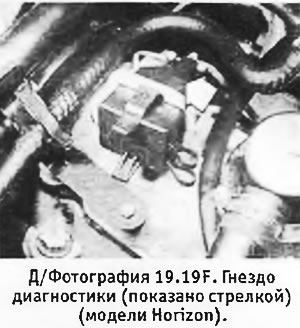
- And. diagnostic sockets (see photo)
 |  |
 |  |
 |  |
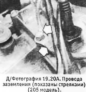
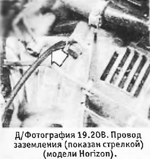
20. Remove the bolts securing the ground wires to the gearbox (see pictures).
 |  |
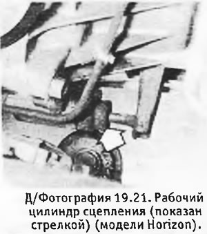
21. On Horizon models, unscrew the bolts securing the clutch slave cylinder and place it to the side so that it does not interfere with (see photo).
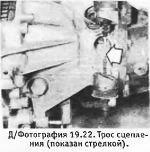
22. On other models, disconnect the clutch cable and remove the pusher (see photo).
23. Disconnect the speedometer cable from the gearbox.
24. Disconnect the gas pedal cable from the injection pump and place it to the side so that it does not interfere.
25. Disconnect the vacuum hose from the vacuum pump and brake booster. Disconnect pressure hose from pump and intake manifold.
26. Disconnect the supply and return fuel hoses from the injection pump (see photo).
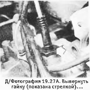
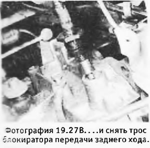
27. Remove the nut (where available) and disconnect the reverse gear lock cable from the top of the gearbox (see pictures). Place it aside so that it does not interfere.
 |  |
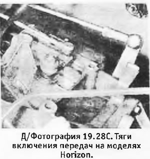
28. Disconnect the gear shift rods from the gearbox. You will need a small open-end wrench to disconnect the tie rods (see photo).
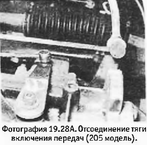 | 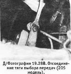 |
29. Unscrew the bolts securing the exhaust system downpipe to the manifold and remove them together with the springs and rings (see photo).
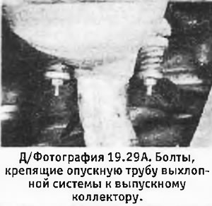 | 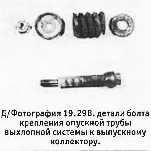 |
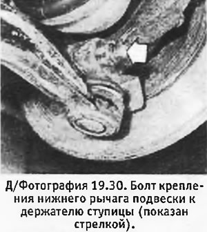
30. Remove the bolts and nuts securing the front lower arms to the hub holders (see photo). Remove the bolts securing the anti-roll bar support.
31. Using the lever, move the suspension arms down one by one so that the ball joints move away from the bottom of the hub holders. Remove ball joint boots (if provided).
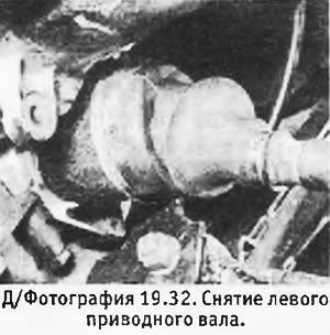
32. Have an assistant pull the left hub out while lowering the left drive shaft from the differential side gear (see photo). Wedge the hub in this position with a block of wood.
33. On pre-July 1984 models, support the left side differential gear with a wooden pin or stick. If you do not do this, the axle wheels may move relative to each other when you remove the right drive shaft.
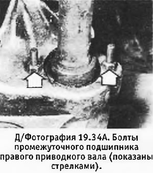
34. Loosen the 2 nuts securing the right drive shaft intermediate bearing to the lower engine support bracket bolted to the cylinder block and turn the bolt heads 90°to release the bearing (see pictures).
 |  |
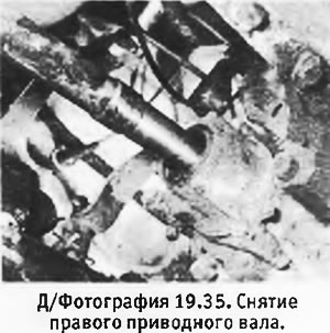
35. Have an assistant pull the right hub out while removing the right drive shaft from the differential side gear (see photo). Wedge the hub in this position with a block of wood.
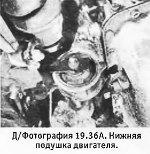
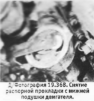
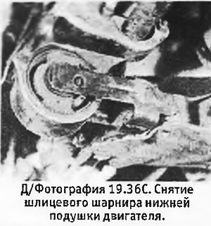
36. Unscrew the nuts from the bolts of the spline joint of the lower engine mount (at the pillow and at the cross), paying attention to the position of the spacers (see pictures).
 |  |
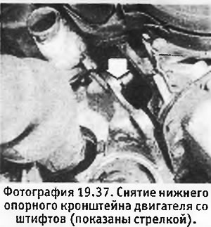
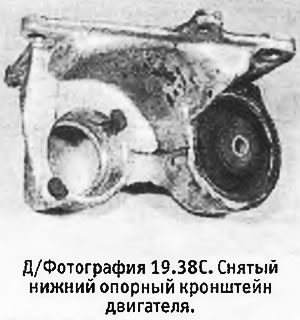
37. Remove the bolts and press the lower engine support bracket off the pins on the cylinder block (see photo).
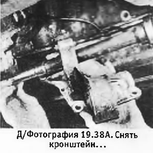
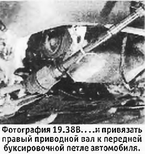
38. Remove the bracket, turn the right drive shaft forward and tie it to the front towing loop (see pictures).
 |  |
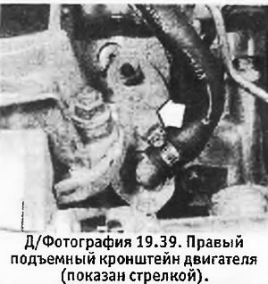
39. Connect the hoist to the engine lifting brackets (see photo) so that the engine with the gearbox can be fixed in a horizontal position by removing their weight from the pillows.
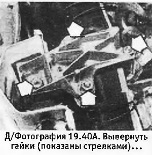
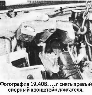
40. Remove the nuts and remove the right engine support bracket (see pictures).
 |  |
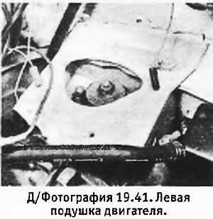
41. Remove the bolt and nut from the left engine mount. Unscrew the nut (nuts) and remove the rubber band (see photo).
42. Lower the engine with the gearbox to the ground, being careful not to damage the equipment remaining in the engine compartment (see pictures).
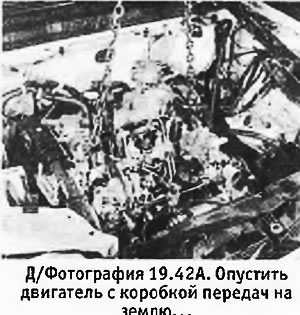 | 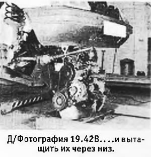 |
43. Pull the engine with the box out from under the car.
44. If after removing the engine with the gearbox you need to roll the machine, you should connect the suspension arms to the hub holders, install the wheels and fix the drive shafts in their normal position with a wire so that they can rotate freely.