
2. Drain the coolant.
3. Remove the battery.
4. Vehicles with XU102C engine. Remove air intake 1 (see illustration 5.0).
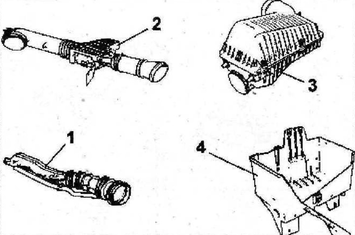
5.0 Remove air intake 1
5. Vehicles with XU10J2 engine. Remove the air filter/mass air flow sensor 2 (see illustration 5.0).
6. Remove the air filter 3 (see illustration 5.0).
7. Remove battery tray 4 (see illustration 5.0).
8. Release the engine wiring harnesses from holders A and B (see arrows in illustration).
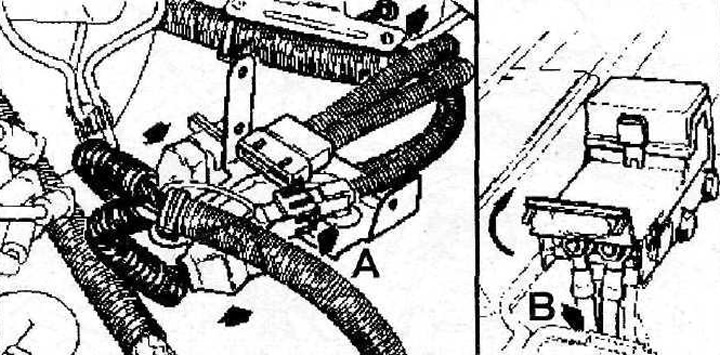
5.8 Release the engine harnesses from holders A and B (see arrows)
9. Vehicles with XU10J2 engine. Release the engine wiring harness from holder C (see arrows in illustration)
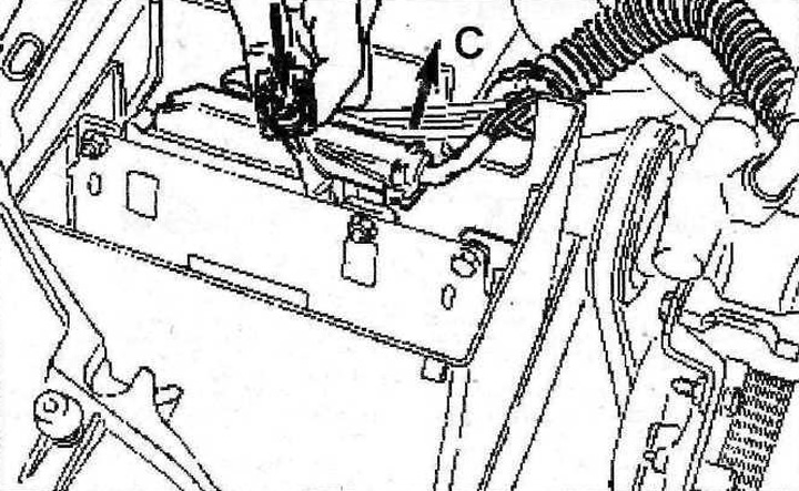
5.9 Release the engine wiring harness from holder C (see arrows). Vehicles with XU10J2 engine
10. Move pump 5 and reservoir 6 of the power steering away from the place of work (see illustration).
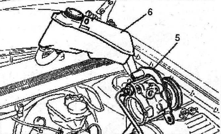
5.10 Move pump 5 and reservoir 6 of the power steering away from the place of work
11. Disconnect, release from the holders all wiring harnesses, hoses and pipelines connected to the power unit or fixed to it and preventing its dismantling.
12. Remove the power unit hangers
13. Press out the pin 7 of the bracket 8 and disconnect the support (see arrows in illustration).
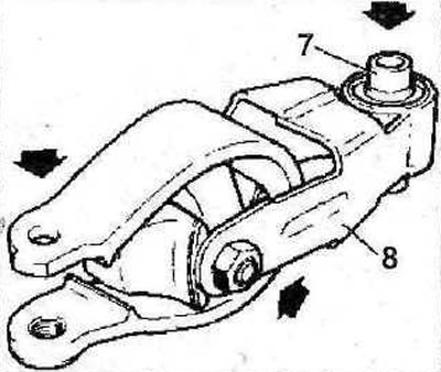
5.13 Press out the pin 7 of the bracket 8 and detach the support (see arrows)
14. Remove the right drive shaft 9 (see illustration).
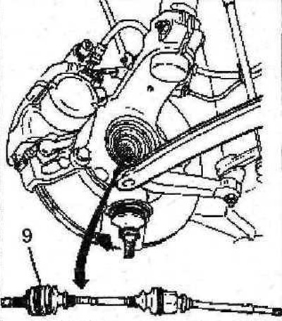
5.14 Remove the right drive shaft 9
15. Disconnect the right suspension support 10 (see illustration)
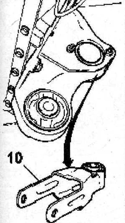
5.15 Disconnect the right suspension support 10
16. Remove the left drive shaft 11 (see illustration).
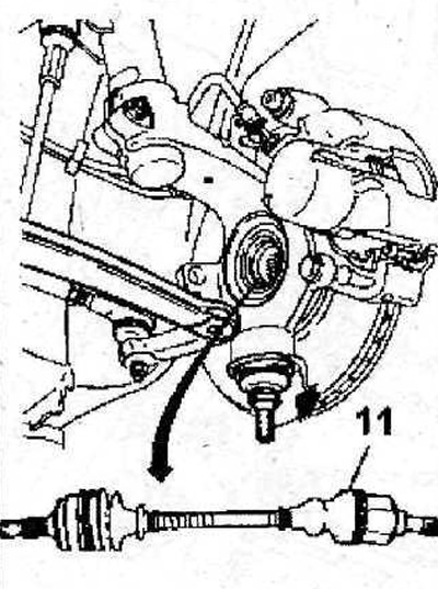
5.16 Remove the left drive shaft 11
17. Disconnect the downpipe (see illustration).
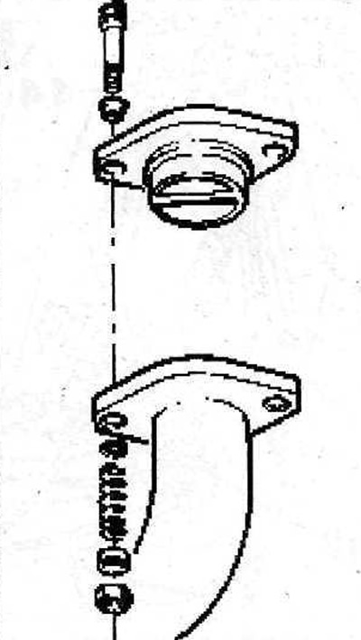
5.17 Disconnect the downpipe
18. Disconnect the speedometer drive cable.
19. Disconnect the air conditioning compressor (if provided) Attention! All work related to the air conditioner should be entrusted to a specialized workshop. Do not open the refrigerant circuit yourself - risk of frostbite!
20. Attach the hooks of a girder or hoist to the engine lugs and carefully lift the engine. to unload his supports (see arrows in illustration).
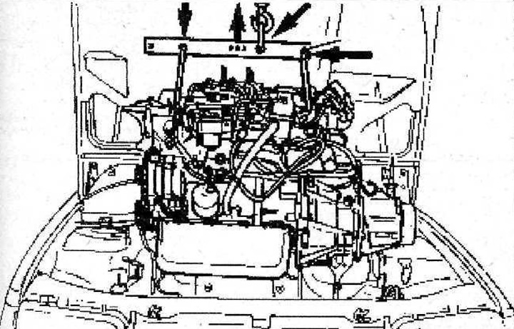
5.20 Attach the hooks of a girder or hoist to the engine lugs and carefully lift the engine to relieve its supports (see arrows)
21. Unscrew the mounting bolts (see arrows in illustration) and remove support 12 of the gearbox.
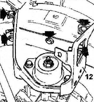
5.21 Unscrew the mounting bolts (see arrows) and remove support 12 of the gearbox. Tightening torque of the support mounting bolts - 30 Nm
22. Unscrew the nut 13 and remove the right engine mount (see illustration).
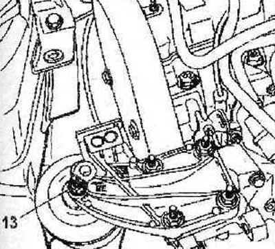
5.22 Unscrew nut 13 and remove the right engine mount. Tightening torque - 45 Nm
23. Carefully remove the engine from the engine compartment.