
Attention! To prevent the pistons from hitting the valves, turn the crankshaft about a quarter of a turn so that the pistons are located approximately in the middle of the cylinder bores.
29. Install the camshaft in its seat.
30. Install bearing caps #2, #3, #4, and #5 using the marks made during removal.
31. Working in a spiral, tighten the bearing cap nuts.
32. Apply a small amount of LOCTITE FORMAJOINT to the outside of #1 bearing cap 6 (see illustration).
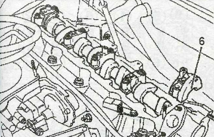
3.32 Apply a small amount of LOCTITE FORMAJOINT grease to the outside of #1 bearing cap 6
33. Tighten the bearing cap nuts to 15 Nm.
34. Tighten bolt 5 with a force of 15 Nm, install oil line 4 in its seat (see illustration 3.8).
35. Drive in a new camshaft oil seal using a suitable mandrel, such as a mandrel «A» 0132-R, pressing it with bolts 1 M10x60 (see illustration).
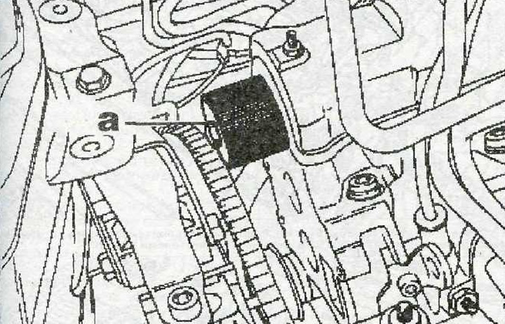
3.35 Drive in a new camshaft oil seal using a suitable mandrel, e.g «A» 0132-R, pressing it with bolts 1 M10x60
36. Install the camshaft gear (see illustration). Tighten the bolts of its fastening with a force of 50 Nm.
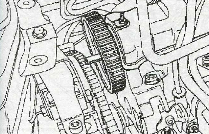
3.36 Install the camshaft gear
37. Vehicles with XU102C engines. Install the fuel pump and tighten its mounting bolts to 20 Nm.
38. Further, the installation of the dismantled components is carried out in the reverse order of removal.
Vehicles with XU10J4R engine
39. Install pushrods (if filmed), each - to its seat, after lubricating them with clean engine oil. Check up ease of a course of pushers in a head of the block of cylinders.
40. Apply a thin coat of engine oil to the bearing journals and cams of each camshaft.
41. Install the camshafts in their seats so that the installation groove 15 of the shaft is in position «three hours», and the installation groove 16 of the second camshaft is in the position «eleven o'clock» (see illustration).
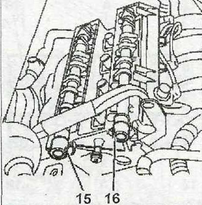
3.41 Install the camshafts in their seats so that the installation groove 15 of the shaft is in position «three hours», and the installation groove 16 of the second camshaft is in the position «eleven o'clock»
42. Make sure the dowel pins 18 are in place (see illustration).
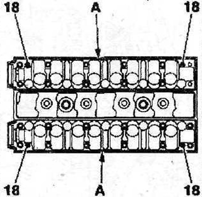
3.42 Check that the dowel pins 18 are in place
43. Apply layer A of SILICONE CATEGORIE 2 around the perimeter of the camshaft bearing housings (see illustration 3.42), install the bearing housings in their seats.
44. Tighten the camshaft bearing housing bolts in several passes in the sequence shown in the illustration:
- 1st pass - tighten the bolts by hand;
- 2nd pass - tighten the bolts with a force of 5 Nm;
- 3rd pass - tighten the bolts to 10 Nm.
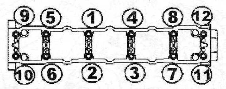
3.44 Tighten the camshaft bearing housing bolts in several passes in the sequence shown
Attention! Cylinder head gasket composite: Minor gasket damage can be repaired by applying SILICONE CATEGORIE 2 sealant.
45. Install covers 12 and 13 of the cylinder head, tighten the bolts of their fastening with a force of 10 Nm in the sequence shown in the illustration.
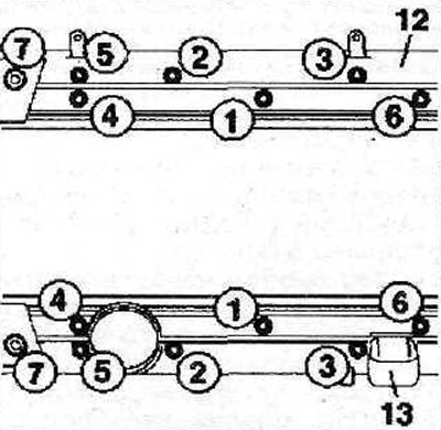
3.45 Install covers 12 and 13 of the cylinder head, tighten the bolts of their fastening with a force of 10 Nm in the specified sequence
46. Further, the installation of the dismantled components is carried out in the reverse order of removal.