
Note. On 1.9L engines, adjusting valve clearances requires removing the camshaft. If it is intended to replace the removed camshaft, it is recommended to record the valve clearances before removing the shaft in order to make the necessary adjustment before installation (see paragraph 12).
Removing
1. Remove the cylinder head cover as described in paragraph 4.
2. Remove the brake vacuum pump as described in chapter 9.
3. Remove the camshaft sprocket as described in paragraph 9. Continue as described under the appropriate subheading.
Engines 1.9 l
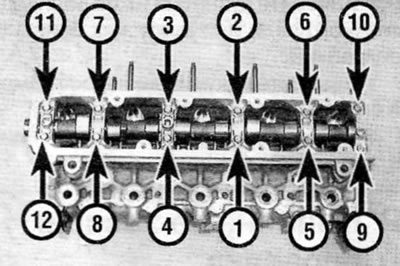
4. Camshaft bearing caps must be numbered (1 to 3); cap #1 is located at the end of the engine on the gearbox side (pic. 11.4). If there is no marking, use white paint or a suitable marker to identify the caps. Also mark each cap in a suitable way to indicate how it is oriented. This will avoid the possibility of improper installation of covers.
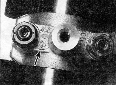
Pic. 11.4. Camshaft bearing caps must be numbered (marked with an arrow) for identification purposes (engines 1.9 l)
5. Loosen the camshaft bearing cap nuts evenly and gradually, loosening one turn per set. This allows you to gradually and evenly remove the force from the valve springs on the bearing caps. As soon as the force is removed, the nuts can be unscrewed completely.
Warning. If the bearing cap nuts are loosened carelessly, the caps may break. If any of the bearing caps fail, the entire cylinder head assembly will need to be replaced; bearing caps are matched to the head and are not supplied separately.
6. Mark the correct orientation of the bearing caps, and then remove them from the cylinder head.
7. Remove the camshaft from the cylinder head and remove the cuff from the end of the camshaft.
8. Prepare eight small clean plastic containers and number them from 1 to 8. Alternatively, divide the large container into eight compartments. Using a rubber suction cup, remove all pushers one by one and place them in the containers provided. Do not confuse pushrods - this can lead to accelerated wear. If necessary, also remove the shim from the top end of the valve stem and store it with the appropriate tappet.
Note. The shim may stick to the inside of the tappet when it is removed. In this case, be careful that it does not fall out when removing the pusher.
Engines 2.0 l
9. Working in the given sequence, evenly and gradually loosen the bolts securing the camshaft bearing housing, releasing one turn per approach (pic. 11.9). This allows you to gradually and evenly remove the force from the valve springs on the bearing housing. As soon as the force is removed, the bolts can be unscrewed completely.
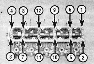
Pic. 11.9. The sequence of releasing the bolts of the camshaft bearing housing (engines 2.0 l)
Warning. If the bearing housing bolts are loosened carelessly, the housing may break. In the event of a bearing housing failure, the entire cylinder head assembly will need to be replaced; the bearing housing is matched to the head and is not supplied separately.
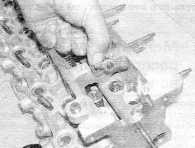
10. Remove the camshaft bearing housing from the cylinder head (pic. 11.10). If the cover dowel pins are not secured in the head, remove them and store them in a safe place along with the body.
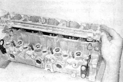
Pic. 11.10. Remove bearing housing...
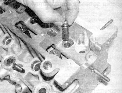
11. Remove the camshaft from the cylinder head and remove the cuff from the end of the camshaft (pic. 11.11).
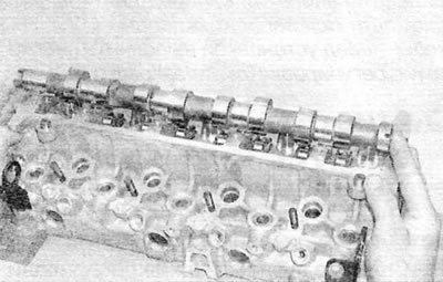
Pic. 11.11.... then remove the camshaft from its original place (shown on removed cylinder head) (engines 2.0 l)
12. Prepare eight small clean plastic containers and number them from 1 to 8. Each container should be deep enough to keep the pushers almost completely submerged in the oil. Remove all valve levers and remove all tappets one by one and place them in the containers provided (pic. 11.12, a, b). Pour clean engine oil into each container so that the tappet is submerged. Do not confuse valve levers and tappets, this can lead to accelerated wear.
Pic. 11.12, a. Remove valve levers...
Pic. 11.12, b....and remove the hydraulic tappets from the cylinder head (engines 2.0 l)
Inspection
13. Inspect the working surfaces of the bearing journals and camshaft cams for signs of wear and scoring. If any of these conditions are present, replace the camshaft. Check the condition of the running surfaces of the bearings on the camshaft journals and in the bearing caps/cylinder head. If the bearing surfaces in the cylinder head show excessive wear, the cylinder head must be replaced.
14. Inspect the surfaces of the tappets/valve levers that contact the camshaft lobes for wear and tear. Replace the pushrod/valve lever if this condition exists. If the running surface is severely scratched, also inspect the corresponding cam on the camshaft for wear, as both parts will most likely be worn. Replace worn elements if necessary.
15. On 2.0 liter engines, if the hydraulic tappets are found to be faulty, they should be replaced.
Installation
Engines 1.9 l
16. If a removed camshaft is reinstalled and the valve clearances are known to be correct, proceed to the next step. Otherwise, adjust the valves as described in paragraph 12, focusing on the clearance values recorded before removing the camshaft. If a new camshaft is used, install it as described in paragraphs 17-23, and then adjust the valve clearances (paragraph 12).
Warning. Before turning the camshaft, make sure the crankshaft is positioned correctly and the pistons are in the middle of the upward stroke.
17. Install each shim on top of the appropriate valve stem.
Warning. Do not mix up the shims, as this will lead to a violation of the adjustment of valve clearances (see paragraph 12).
18. Copiously lubricate the hydraulic tappet holes in the cylinder head and the tappets themselves. Carefully insert the tappets into the bores in the cylinder head, ensuring that each tappet is seated in its original hole. Some care will be required to insert the tappets into the holes without being skewed.
19. Lubricate the bearing journals and camshaft cams with clean engine oil of the prescribed grade. Then install the shaft in its original place in the cylinder head.
20. Temporarily install the toothed pulley on the end of the camshaft and position it so that the mounting hole in the hub is aligned with the corresponding cutout in the cylinder head. Make sure the crankshaft is still at 90°before TDC and the pistons are in the middle of the upstroke.
21. Install the center bearing cap properly as previously noted, then screw on the nuts and tighten them two or three turns.
22. Apply sealant to the outer bearing caps at the locations shown (pic. 11.22). Install them in the correct position and tighten the nuts two or three turns.
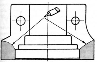
Pic. 11.22. Apply sealant to the areas shown on the outer camshaft bearing caps (engines 1.9 l)
23. Evenly and progressively tighten all nuts to the prescribed torque, making sure that the camshaft remains in the correct position.
Warning. If the bearing cap nuts are tightened carelessly, the caps may break. If any of the bearing caps fail, the entire cylinder head assembly will need to be replaced; bearing caps are matched to the head and are not supplied separately.
24. Coat the sealing lips of the new seal with clean engine oil and install the seal on the end of the camshaft, making sure that the sealing edge is facing inward. Press down on the lip so that it is flush with the end surface of the camshaft bearing cap.
25. Install the camshaft sprocket as described in paragraph 9.
26. Install the brake vacuum pump as described in chapter 9.
27. Install the cylinder head cover as described in paragraph 4.
Engines 2.0 l
28. Liberally lubricate the hydraulic tappet holes in the cylinder head and valve levers. Properly secure the valve levers to the tappets and carefully insert the tappets into the mounting holes in the cylinder head, ensuring that each tappet is installed in the original hole.
29. Lubricate the bearing necks and camshaft cams and valve levers with clean engine oil of the prescribed grade.
30. Make sure the crankshaft is still at 90°before TDC and the pistons are midway up.
31. Clean and dry the mating surfaces of the camshaft bearing housing and cylinder head. Apply sealant in a narrow bead (Peugeot/Citroen recommends Autojoint NOIR) onto the housing mating surface as shown (pic. 11.31).
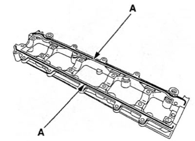
Pic. 11.31. Apply sealant in a narrow bead (A) onto the mating surface of the camshaft bearing housing as shown (engines 2.0 l)
32. Properly install the camshaft into the bearing housing, and then, making sure that the dowel pins are in place, install the camshaft assembly with the bearing housing on the cylinder head.
33. Screw in bolts of fastening of the case of bearings and tighten all bolts by force of a hand. Working in sequence, evenly and progressively tighten the bolts to pull the housing into position in the cylinder head (pic. 11.33). Once the body is in contact with the head, working in the prescribed sequence, tighten the bolts to the prescribed torque.
Pic. 11.33. The sequence of tightening the bolts of the camshaft bearing caps (engines 2.0 l)
Warning. If the bearing housing bolts are tightened carelessly, the housing may break. In the event of a bearing housing failure, the entire cylinder head assembly will need to be replaced; the bearing housing is matched to the head and is not supplied separately.
34. Coat the sealing lips of the new seal with clean engine oil and install the seal on the end of the camshaft, making sure that the sealing edge is facing inward. Press down on the lip so that it is flush with the end surface of the camshaft bearing cap.
35. Install the camshaft sprocket and hub as described in paragraph 9.
36. Install the brake vacuum pump as described in chapter 9.
37. Install the cylinder head cover as described in paragraph 4.