



Table of contents: Removal (1.9 L engines) 🠇 Installation (1.9 L engines) 🠇 Removal (2.0 L engines) 🠇 Pulley without green mark 🠇 Pulley with green mark 🠇 Installation (2.0 L engines) 🠇
Removal (1.9 L engines)
1. Remove the accessory drive belt as described in chapter 1B.
2. Remove the four crankshaft pulley mounting bolts and remove the pulley, making note of how it is installed.
Installation (1.9 L engines)
3. Install the pulley onto the end of the crankshaft, orienting it correctly. Apply a locking compound (peugeot/Citroen recommends the use of Loctite Frenetanch) onto the threads of the corresponding bolts, then screw in the bolts and tighten them to the specified torque.
4. Install and tension the accessory drive belt as described in chapter 1B.
Removal (2.0 L engines)
5. Remove the accessory drive belt as described in chapter 1B.
6. Now it is necessary to determine the type of pulley installed, as there are two different removal and installation procedures accordingly.
7. From under the wheel arch, look at the flat face of the pulley. If it has a mark made with green paint, it is a later type pulley. If there is no mark, it is an early type pulley. Proceed as described below depending on the pulley type.
Pulley without green mark
8. To prevent the crankshaft from turning when the pulley mounting bolt is loosened, the flywheel ring gear should be locked using a suitable tool made from a steel strip. Release the power steering fluid lines from the clamps on the cover at the base of the front section of the transmission case. Remove the flywheel housing cover and use the bolt to secure the tool through the lower threaded hole in the front section flange of the transmission housing so that it engages the teeth of the ring gear.
Tip: A flywheel ring gear locking tool can be made from a short steel strip bent at a right angle. Cut a slot in the top section and bend this section back to engage with the ring gear teeth. File the folded edge to give it a tooth profile. Drill a hole in the lower section so that the tool can be bolted to the flange of the front section of the transmission case.
9. Using a suitable socket head and extension, loosen the bolt, remove it together with the washer and remove the pulley from the end of the crankshaft (figure 5.9). If the pulley is tight, the crankshaft can be released using a suitable puller. If using a puller, install the pulley mounting bolt without the washer to avoid damaging the crankshaft when tightening the puller.
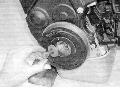
Figure 5.9. Unscrew the bolt, remove it together with the washer and remove the crankshaft pulley (2.0 L engines)
Pulley with green mark
10. Align the engine/camshaft timing assembly mounting holes as described in paragraph 3, and lock the crankshaft and camshaft timing pulley. The later type crankshaft sprocket has a wider woodruff keyway. When the pulley mounting bolt is loosened, the toothed pulley can rotate on the crankshaft as far as the wider keyway allows. This allows some lateral movement of the timing pulley for precise adjustment of the timing belt tension. Therefore, when releasing the pulley bolt, it is necessary that the flywheel and camshaft are locked in the engine assembly/valve timing position, otherwise the toothed pulleys will turn slightly and the valve timing will be "off".
11. To prevent the crankshaft from turning when the pulley mounting bolt is loosened, make and install a flywheel ring gear locking tool as described in paragraph. 8. Do not attempt to use engine assembly/timing position locking tools to prevent rotation when the bolt is loosened.
12. Using a suitable socket head and extension, remove the bolt and washer, then slide the pulley off the end of the crankshaft. If the pulley is tight, the crankshaft can be released using a suitable puller. If using a puller, install the pulley mounting bolt without the washer to avoid damaging the crankshaft when tightening the puller.
Installation (2.0 L engines)
13. When working with a later type pulley, ensure that the engine/camshaft timing assembly mounting holes are still aligned as described in paragraph 3, and the toothed pulleys of the crankshaft and camshaft were locked.
14. Install the pulley onto the end of the crankshaft.
15. Thoroughly clean the pulley mounting bolt threads, then apply locking compound to the bolt threads (peugeot/Citroen recommends using Loctite Frenetanch).
16. Screw in the crankshaft pulley mounting bolt (don't forget to put a washer underneath). Tighten the bolt to the specified torque, then turn it the rest of the way to the specified angle, holding the crankshaft from turning with the tool used for removal. Please note that different tightening torque values and angles are listed in the "Specifications" depending on the pulley type.
17. Remove the flywheel ring gear locking tool and, if applicable, the tools used to lock the crankshaft and camshaft timing pulleys.
18. Install the cover onto the front section of the transmission case and secure the power steering fluid lines.
19. When working with a later type pulley, install the upper timing belt cover as described in paragraph 6.
20. Install and tension the accessory drive belt as described in chapter 1B.