
Note. Do not attempt to crank the engine when the crankshaft/camshaft/high pressure fuel pump is stuck. If the engine is to be left in this state for an extended period of time, it is recommended that warning labels be placed on the front panel and in the engine compartment. This will reduce the risk of accidental cranking of the engine by the starter, which can damage the engine if the shafts are locked.
Engines 1.9 l
1. Locating holes are drilled in the camshaft sprocket hub, injection pump sprocket hub and flywheel. The holes are used to set the correct position of the crankshaft, camshaft and high pressure fuel pump, to prevent possible collision of valves and pistons when installing the cylinder head, and to correctly set the valve timing / fuel injection advance in the high pressure fuel pump when installing the timing belt. When the holes are aligned with the corresponding holes in the cylinder head and cylinder block (whichever is applicable), bolts/rods of the appropriate diameter can be inserted to lock the camshaft, high pressure fuel pump and crankshaft against unintended rotation. Then proceed as described below.
2. To gain access to the toothed pulleys, remove the upper and intermediate timing belt covers as described in paragraph 6.
3. Using a suitable socket and extension, rotate the crankshaft at the pulley bolt until the holes in the hubs of the camshaft pulleys and the injection pump are aligned with the mounting holes in the cylinder head/pump. Keep in mind that the crankshaft should only be turned clockwise (when viewed from the right side of the car).
4. With the hole in the camshaft sprocket correctly aligned, pass a 8mm bolt or drill bit through the hole in the front left flange of the cylinder block, behind the starter, and insert it into the locating hole on the back of the flywheel (pic. 3.4). Keep in mind that it may be necessary to turn the crankshaft slightly to align the holes.
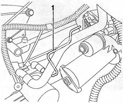
Pic. 3.4. Pass bolt/drill (special tool shown (pos. 1) through the hole in the flange of the cylinder block (in the figure, the starter is moved forward for clarity) and insert it into the hole on the back of the flywheel
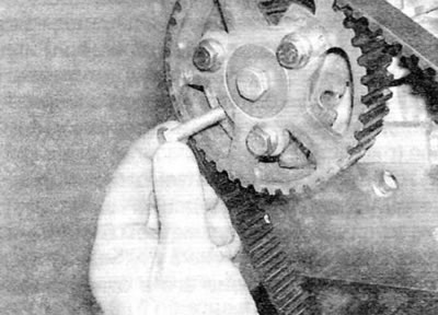
5. Having set the flywheel correctly, lock the camshaft pulley by passing a bolt or drill with a diameter of 8 mm through the mounting hole in the hub of the toothed pulley and insert it into the hole in the cylinder head (pic. 3.5).
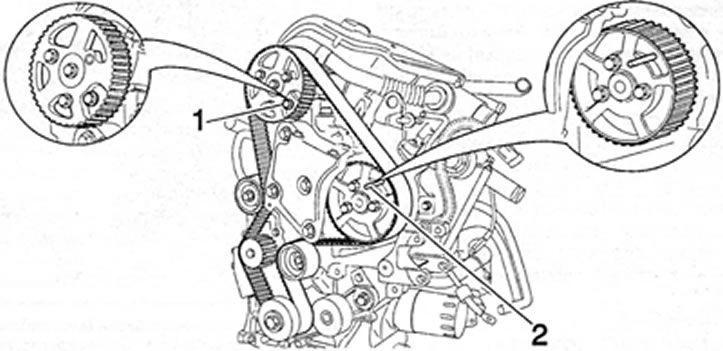
Pic. 3.5. Lock the camshaft and high pressure fuel pump sprockets by inserting bolts/drills (pos. 1 and 2) (engines 1.9 l)
6. Lock the injection pump sprocket by running a 6 mm bolt or drill through the locating hole in the sprocket hub and inserting it into the hole in the pump.
7. The crankshaft, camshaft and high pressure fuel pump are now locked and prevented from turning unintentionally.
Engines 2.0 l
8. Locating holes, or slots, are located in the flywheel and sprocket hub or camshaft sprocket. The holes/slots are used to drive the crankshaft and camshaft to TDC for No. 1 and No. 4 pistons. This allows the valve timing to be maintained during operations that require the removal and installation of the timing belt and, on later engines, the installation of the crankshaft pulley. When the holes/slots are aligned with the corresponding holes in the cylinder block and cylinder head, bolts/rods of the appropriate diameter can be inserted to lock the crankshaft and camshaft against unintended rotation.
9. The HDI fuel system used on these engines is not equipped with a conventional high pressure diesel injection pump. Instead, a high pressure fuel pump is used, which does not require injection advance adjustment. Therefore, the position of the fuel pump sprocket (and therefore the fuel pump itself) relative to the crankshaft and camshaft does not matter.
10. To align the mounting holes for the engine/camshaft assembly, proceed as described below.
11. Remove the upper timing belt cover as described in paragraph 6.
12. Using a suitable socket and extension, rotate the crankshaft at the pulley bolt until the alignment groove in the camshaft sprocket hub is aligned with the alignment hole in the cylinder head. Keep in mind that the crankshaft should only be turned clockwise (when viewed from the right side of the car). Use a small mirror to observe the position of the alignment slot in the toothed pulley hub (pic. 3.12, a, b). When the groove is aligned with the mounting hole in the cylinder head, the engine is at TDC for pistons #1 and #4.
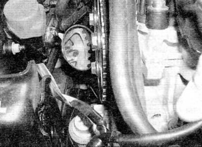
Pic. 3.12, a. Use a mirror to observe the alignment groove in the camshaft sprocket hub (engines 2.0 l)
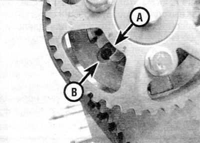
Pic. 3.12b. Mounting groove (A) in the hub of the camshaft pulley, aligned with the mounting hole (IN) in the cylinder head (engines 2.0 l)
13. Pass a bolt, rod or drill with a diameter of 8 mm through the hole in the left flange of the cylinder block near the starter and insert into the mounting hole in the flywheel (if necessary, turn the crankshaft slightly in one direction or another) (pic. 3.4).
14. Pass a bolt, rod or drill with a diameter of 8 mm through the groove in the hub of the camshaft pulley and insert into the corresponding hole in the cylinder head (pic. 3.14).
Pic. 3.14. Pass a bolt/drill through the hole in the hub of the camshaft pulley and insert it into the cylinder head (engines 2.0 l)
15. Now the crankshaft and camshaft are locked and their unwanted turning is excluded.