



Table of contents: 1.9L engines 🠇 2.0L engines 🠇
1.9L engines
Removal the top cover
1. Disconnect the ground cable from the battery (see "Disconnecting the battery").
2. Release the clamp in the center of the engine cover and remove the screw on the right. Remove the engine cover (figure 4.1, a-c).
3. Fully apply the parking brake. Raise the front of the vehicle and support it securely (see "Lifting and installing the car on supports"). Remove the right front wheel.
4. To gain access to the right end of the engine, remove the plastic wheel arch liner. The locker is fixed with various screws and fasteners. Release all fasteners and remove the mudguard from under the front fender. If necessary, release the coolant hoses under the fender to allow easier access later.
5. Disconnect the quick release couplings of the fuel supply and return hoses at the connections near the fuel pump using a small screwdriver to release the retaining clip. Seal open ports to prevent dirt from entering using small plastic bags or "fingers" cut from clean rubber gloves.
6. Release the two hoses from the clips on the upper timing belt cover and move them to the side (figure 6.6).
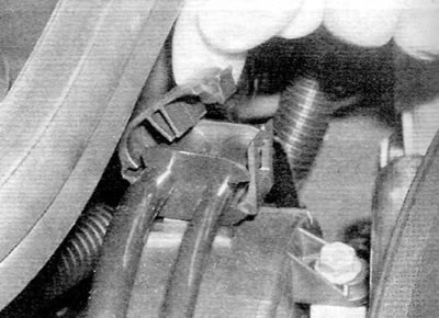
Figure 6.6. Release the fuel lines from the clamps on the upper timing belt cover (1.9 L engines)
7. Connect the engine lifting device to the two lifting brackets on the cylinder head. Raise the lifting device enough to relieve the engine mounts.
8. For additional stability, place a jack under the right side of the engine, placing a block of wood on the jack head. Raise the jack just enough to make contact with the oil pan.
9. Remove the three bolts securing the upper bracket of the right engine/gearbox mount to the lower bracket (on the engine). Unscrew the single nut securing the upper bracket to the rubber support. Remove the top bracket from the rubber support and lower the bracket (on the engine).
10. Remove the two nuts and tie bolts securing the rear engine/gearbox mount tie rod to the support bracket on the subframe and to the rear of the cylinder block. Release the tie and remove it from the support brackets.
11. After removing the two engine mounts, alternatively raise and lower the lifting device and jack under the engine as far as necessary to gain access to the timing belt cover mounting bolts.
12. Unscrew the bolt securing the top cover to the cylinder head cover (figure 6.12)
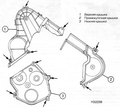
Figure 6.12. Location of timing belt cover mounting bolts (marked with arrows) (1.6 l engines)
13. Remove the two bolts at the connection between the top cover and the bottom cover: one in the center just below the engine support bracket and one on the outer edge. Keep in mind that the bolt on the outer edge also serves to secure the coolant pump. To prevent coolant leakage after removing the cover, screw in the bolt with a 5.0mm spacer on it and tighten it securely.
14. Remove the remaining bolt directly above the high pressure fuel pump sprocket.
15. Release the mounting tabs, release the top section from behind the intermediate cover and remove the top cover.
Removal the intermediate cover
16. Remove the top cover as described above.
17. Remove the remaining bolt at the base of the cover just below the engine support bracket.
18. Release the mounting tabs and remove the intermediate cover.
Removal the bottom cover
19. Remove the top and intermediate covers as described above.
20. Remove the crankshaft pulley as described in paragraph 5.
21. Remove the two remaining bolts on the edge of the cover, one on each side of the crankshaft pulley mounting area.
22. Remove the cover from the front of the engine.
Installation
23. Installation of all covers is carried out in the reverse order of removal, correctly fix each section of the cover and securely tighten the cover mounting bolts. Connect all disturbed hoses and secure them with appropriate clamps. Tighten all nuts/bolts to the specified torque (if given). Finally, fill and bleed the fuel system as described chapter 4B.
2.0L engines
Caution: Before starting the procedure, please read the safety precautions contained in paragraph 1.
Removal the top cover
24. Disconnect the ground cable from the battery (see "Disconnecting the battery").
25. Turn the four plastic clips 90° and remove the engine cover (figure 6.25, a, b).
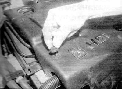
Fig. 6.25, a. Turn each locking pin a quarter turn to release it...
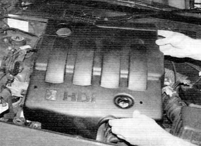
Figure 6.25, b....and then remove the engine cover (2.0 L engines)
26. Fully apply the parking brake. Raise the front of the vehicle and support it securely (see "Lifting and installing the car on supports"). Remove the right front wheel.
27. To gain access to the right end of the engine, remove the plastic wheel arch liner. The locker is fixed with various screws and fasteners. Release all fasteners and remove the mudguard from under the front fender. If necessary, release the coolant hoses under the fender to allow easier access later.
28. Disconnect the quick-release couplings of the fuel supply and return hoses at the connections near the fuel pump using a small screwdriver to release the retaining clip (6.28). Seal the open ports to prevent dirt from entering using small plastic bags or "fingers" cut from clean rubber gloves.
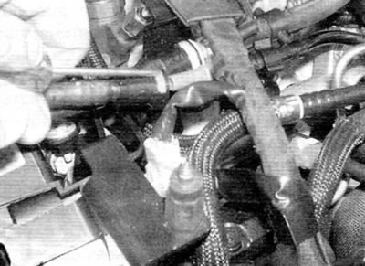
Figure 6.28. Disconnect the quick-release couplings of the fuel supply and return hoses (2.6 L engines)
29. Release the two hoses from the clips on the upper timing belt cover and move them to the side (figure 6.29).
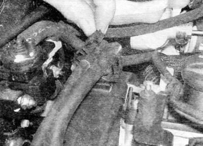
Figure 6.29. Release the two hoses from the clamps on the upper timing belt cover (2.0 L engines)
30. On early engines, remove the EGR solenoid valve support bracket mounting bolt and move the valve to the side.
31. Unscrew the two bolts securing the reinforcing bracket of the right support to the body and remove the bracket together with the accelerator pedal position sensor (on later engines) (figure 6.31).
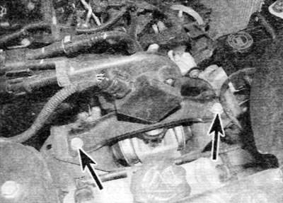
Figure 6.31. Remove two bolts (marked with arrows) and remove the reinforcement bracket and pedal position sensor (late 2.0L engines)
32. Attach the engine lifting device to the two lifting brackets on the cylinder head. Raise the lifting device enough to relieve the engine mounts. For added stability, place a jack under the right side of the engine, placing a block of wood on the jack head. Raise the jack just enough to make contact with the oil pan.
33. Remove the three bolts securing the upper bracket of the right engine/gearbox support to the lower bracket (on the engine).
34. Remove the domed buffer nut, then remove the single nut securing the upper bracket to the rubber mount. Remove the upper bracket from the rubber mount and the lower bracket (on the engine).
35. Loosen the two nuts and remove the tie rod bolts securing the rear engine/gearbox mount to the support bracket on the subframe and to the rear of the cylinder block. Release the tie and remove it from the support brackets.
36. After removing the two engine mounts, alternatively raise and lower the lifting device and jack under the engine as far as necessary to gain access to the timing belt cover mounting bolts.
37. Unscrew the bolt securing the top cover to the cylinder head cover (figure 6.37).
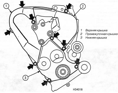
Figure 6.37. Location of timing belt cover mounting bolts (marked with arrows) (2.0 L engines)
38. Remove the top bolt on the edge of the cover, closest to the engine compartment bulkhead.
39. Remove the lower bolt on the cover on the bulkhead side, at the joint between the upper and lower covers. Keep in mind that this bolt also holds the coolant pump. To prevent coolant leakage after removing the top cover, install the bolt with a 17.0mm long spacer and tighten it securely.
40. Remove the remaining bolt in the center of the cover, just above the engine support bracket.
41. Unhook the top cover from the intermediate cover and remove the top cover.
Removal the intermediate cover
42. Remove the top cover as described above.
43. Remove the top bolt on the top edge of the intermediate cover.
44. Remove the two remaining bolts in the connection between the intermediate cover and the lower cover, and then remove the intermediate cover.
Removal the bottom cover
45. Remove the crankshaft pulley as described in paragraph 5.
46. Remove the top and intermediate covers as described above.
47. Remove the two remaining bolts on the edge of the cover, one on each side of the crankshaft pulley.
48. Remove the cover from the front of the engine and remove it.
Installation
49. Installation of all covers is carried out in the reverse order of removal. Correctly secure each section of the cover and tighten the cover mounting bolts securely. Connect all disturbed hoses and secure them with appropriate clamps. Tighten all nuts/bolts to the specified torque (if given). Finally, prime and bleed the fuel system as described in chapter 4B.