



Table of contents: Models before September 1986. 🠇 Models from September 1986. 🠇 All models 🠇 Only for models produced before…🠇 Cylinder head (xUD7T engine) -…🠇 Cylinder Head Gasket Identification…🠇 Cylinder head and exhaust manifold…🠇
1. Perform the operations specified in section 5, paragraphs 1-9.
2. Remove the engine mudguard under the right front wheel arch. To create more room to work, drain the cooling system (see chapter 2) and disconnect the lower radiator hose from the water pump inlet.
3. Disconnect the negative cable from the battery.
4. If necessary, remove the timing belt from the fuel injection pump sprocket and turn the engine 1/4 turn in either direction. In this case, all pistons will move down to half of the cylinders.
19. Remove the bolts securing the exhaust downpipe to the exhaust manifold. Disconnect the pipe and remove the springs and rings.
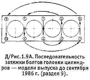
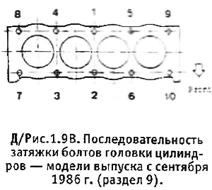
20. Gradually unscrew the cylinder head bolts in the reverse order to that shown in Figure 1.9. Remove the bolts and washers.
21. Rock the cylinder head to separate it from the cylinder block and the dowel pin. The Peugeot tool used for this purpose consists of two metal rods with ends bent at right angles (see Figure 1.7).
22. Remove the cylinder head from the block. Remove its gasket.
23. Don't throw away your old pad until you get a new one. The correct gasket thickness is calculated after determining the piston protrusion at TDC
24. Clean the contact surfaces of the block and cylinder head from traces of the old gasket (it is best to use a blunt tool made of soft material so as not to damage the surface). Clean the cylinder head bolt threads and the bolt holes in the cylinder block.
25. Check that the timing belt has been removed from the fuel injection pump sprocket and turn the engine so that pistons NN 1 and 4 are in the TDC position. Install a dial gauge on the cylinder block and set it to zero on the block surface. Move the instrument probe to the center of piston No. 1 and slowly turn the crankshaft back and forth so that the piston moves from the TDC position. Record the maximum piston protrusion value that the instrument shows (see photo).
26. Repeat the above procedure on piston No. 4, then turn the crankshaft half a turn (180°) and take measurements on pistons No. 2 and 3.
27. If you do not have a dial gauge, the piston protrusion can be measured using a ruler and feeler gauges or a vernier caliper, but these methods provide less accurate results.
28. Determine the maximum piston protrusion and use it to determine the correct shim thickness using the following table:
| Piston protrusion value | Gasket marking |
| 0.54-0.65 mm | 1 notch or 1 hole (for factory installation only - when replacing, select a gasket of the next thickness class) |
| 0.65-0.77 mm | 2 notches or 2 holes |
| 0.77-0.82 mm | 3 notches or 3 holes |
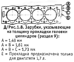
Please note that the notch or hole on the gasket axis (see Figure 1.8) serve only to indicate that the gasket is only intended for 1.7L (XUD 7) engines and has nothing to do with the gasket thickness.
29. Turn the crankshaft clockwise (when looking from the timing belt side) so that pistons NN 1 and 4 pass through BDC and rise to the middle of their cylinders. Pistons NN 2 and 3 will also stop in the middle of their cylinders, but in the lowering phase.
30. Install a gasket of the required thickness on the block so that the identification notches or holes are on the flywheel side (see photo). Check that the dowel pin is in place on the block (from the timing belt side).
Models before September 1986.
Note: Before tightening the cylinder head bolts, refer to the notes at the beginning of this section to ensure that your engine has the old style bolts. If this is not the case, proceed to paragraph 33.
31. Lower the cylinder head onto the block.
32. Apply lubricant to the threads and contact surfaces of the bolts, insert them together with the washers (convex side up) and tighten in the sequence shown in D/Figure 1.9A, in three stages (see Specifications).
Models from September 1986.
Note: Before tightening the cylinder head bolts, refer to the notes at the beginning of this section to ensure that your engine has the new type of bolts. If this is not the case, return to paragraph 31.
33. Thoroughly clean the bolt holes in the cylinder head using a suitable tap (M12x1.5).
34. Lower the cylinder head onto the block.
35. Apply lubricant to the threads and contact surfaces of the new bolts and install new washers. Insert the bolts and tighten them in the sequence shown in D/Figure 1.9B, in three stages (see Specifications).
All models
36. Check valve clearances (see section) and adjust them if necessary. This must be done even if you adjusted the clearances with the cylinder head removed, as they may change slightly after installation.
37. Lubricate the contact surfaces of the exhaust manifold and the exhaust downpipe with high-temperature grease, connect the pipe to the manifold and install the bolts together with their springs, rings and self-locking nuts. On 1.9L engines, the bolts have a flange to ensure proper spring compression. On 1.7L engines, gradually tighten the bolt nuts until approximately 4 threads are exposed on each bolt and the springs are compressed to a length of 23.5 mm.
38. Check that the woodruff key is in place on the camshaft and then install the sprocket and its bolt. Tighten the bolt to the required torque, holding the camshaft with a wrench placed on a special protrusion between the 3rd and 4th cams.
39. Turn the camshaft so that the tops of cams 4 and 6 (counting from the flywheel) looked down.
40. Turn the crankshaft 1/4 turn clockwise so that pistons 1 and 4 are at TDC, and insert a rod into the flywheel to set the TDC position. Do not turn the crankshaft counterclockwise, since this will cause pistons NN 2 and 3 to pass through TDC and hit valves NN 4 and 6.
41. Align the holes and install the M8 bolt on the camshaft sprocket.
42. Install the valve cover with a new gasket.
43. Apply thread locking fluid to the bolt threads and then install and tighten one of the upper right engine support bracket bolts. Install and tighten the tensioner adjustment bolt. Loosen the tensioner pivot nut.
44. Install the timing belt and adjust its tension (see section 4, paragraphs 20-25).
45. Connect the fuel bypass pipe to the high-pressure fuel pump.
46. Connect the wires to the glow plugs.
47. Install the left engine lift bracket.
48. Connect the fuel pipes to the injectors and tighten the fitting nuts.
49. Connect the crankcase ventilation hose to the valve cover. Connect the wiring to the diagnostic socket or to the oil level sensor.
50. Install the brake booster vacuum pump (see chapter 8). Where applicable, install the power steering pump drive belt and adjust its tension.
51. Connect the air intake hose to the intake manifold.
52. Install the oil filler plug/breather.
53. Clean the contact surfaces of the thermostat housing, install it with a new gasket and tighten the mounting bolts. Install 2 small hoses.
54. Connect the heater hose to the cylinder head.
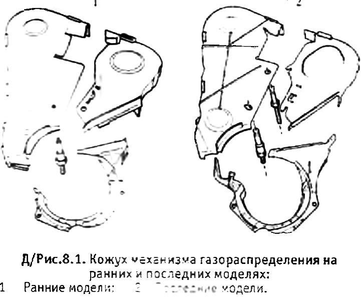
55. Install the timing case sections.
56. Install the right engine support bracket and tighten the mounting nuts. Disconnect the hoists from the engine or remove the jack.
57. Install the air cleaner (see chapter 3).
58. Connect the negative cable to the battery.
59. Fill the cooling system with liquid (see chapter 2).
60. Lower the car to the ground.
Only for models produced before September 1986.
61. Start the engine and let it run for 10 minutes at 3000 rpm, then turn on the ignition and let the engine cool for at least 2 hours.
62. Remove the cap of the expansion tank of the cooling system in order to relieve the pressure from the system, and then reinstall the cap.
63. Working in the correct sequence, loosen each cylinder head bolt 90° in turn, and then tighten the bolts to the final torque specified in Specifications (see photo).
Cylinder head (xUD7T engine) - removal and installation
3. Follow the instructions above, but before removing the cylinder head, disconnect the following additional parts:
- a. Turbocharger fuel supply and return lines.
- b. Hose connecting the intake manifold to the fuel injection pump (see photo).
- c. Fuel heater (if installed).
- the turbocharger itself can be removed together with the manifolds.
3. After installing the cylinder head and before starting the engine for the first time, prime the turbocharger lubrication circuit by disconnecting the shut-off solenoid wire from the fuel pump and turning the engine with the starter 3 times (10 seconds each time).
Cylinder Head Gasket Identification - All Models
4. In addition to the three shim thicknesses listed above, you may come across a shim marked with 4 notches or 4 holes. This gasket is installed on remanufactured engines where the pistons protrude above the cylinder block by more than 0.84 mm.
5. The cylinder head gasket on the XUD7T engine has two notches on the center axis ("E" in Figure 1.8). The thickness of this gasket is still determined by the number of notches in its corner.
Cylinder head and exhaust manifold (engines XUD7T/XUD7TE) - modification
1. Since January 1991. (identification number 70250000) all XUD7T/XUD7TE engines are equipped with a modified cylinder head, reinforced in the area of the water jacket channels. It should be noted that the modified cylinder head was supplied as a replacement by specialized Peugeot centers even before this date.
2. The differences between the old and new cylinder heads are shown in the figure 8.6.
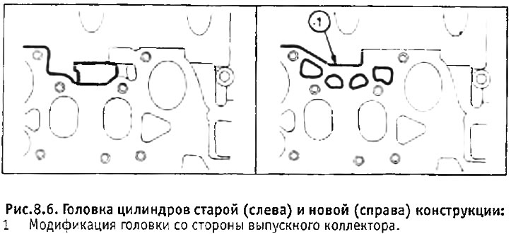
3. The new cylinder head must be installed together with a new exhaust manifold and gasket. The new exhaust manifold can be identified by its 4 individual ports instead of the two typical of earlier manifolds.
4. If you are experiencing coolant leakage on early models, it may be caused by a leaking cylinder head gasket on the exhaust manifold side. This problem can be eliminated by installing a new cylinder head with a new exhaust manifold and gaskets.