



Table of contents: Modifications to exhaust valves and…🠇 XUD7T/L Engine - Modifications 🠇 Valve stem seals - all engines with…🠇
1. With the cylinder head removed (see previous section) remove the camshaft.
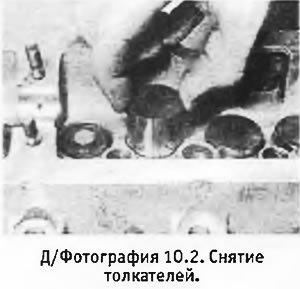
2. Remove the tappets along with their washers and arrange them in order to avoid confusion (see photo).
3. Disconnect the remaining fuel bypass pipes and unscrew the injectors. Remove the special washers.
4. Disconnect the wires from the glow plugs and unscrew them.
5. Unscrew the nuts and bolts and remove the cylinder heads, intake and exhaust manifolds. Remove the exhaust manifold gaskets.
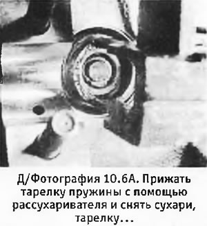
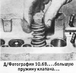
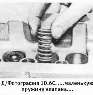
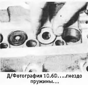
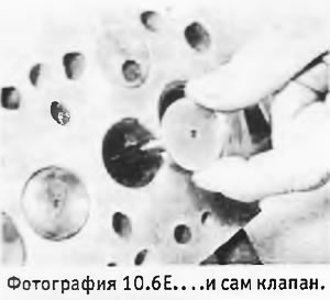
6. Using a valve spring compressor, press down on the spring plate of one of the valves to access the valve springs. The valves are deep, so you may need to extend the end of the valve spring compressor using a tube with a "window" cut in it to gain access to the valve springs. Remove the crackers and valve spring compressor. Remove the valve retainer, large and small valve springs, and spring seat, then pull the valve out of the cylinder head (see photos). Repeat the above procedure on the remaining 7 valves, placing the valves and their associated parts in order to avoid confusion. If necessary, remove the plug from the valve timing hole.
 |
 |
 |
 |
 |
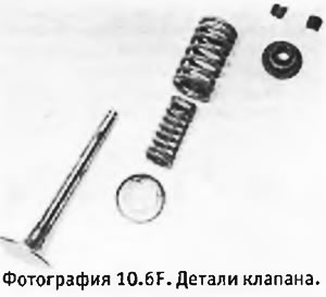 |
Note: On models produced since 1989 (i.e., approximately since September 1988.) the valves have one spring instead of the two previously used).
Modifications to exhaust valves and valve seats on late models
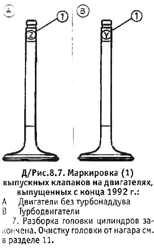
Since the end of 1992, all engines have been equipped with the same exhaust valves and valve seats as the XUD9TE engine. To accommodate the thicker exhaust valve head while maintaining the same compression ratio, the exhaust valve seats are recessed 2.5 mm instead of the previous 2.0 mm.
Cylinder heads with new type exhaust valves and seats can be identified by a 9.0 mm diameter groove in the lug above the glow plug (on older engines the groove diameter is 7.0 mm).
For markings on new type exhaust valves, see. in D/Figure 8.7.
8. Clean all parts and inspect them for wear. Prepare new gaskets for the cylinder head, manifolds, valve cover and thermostat housing. Inspect the head for cracks and other damage.
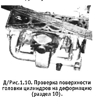
9. Using a ruler and feeler gauges, check the cylinder head surface for distortion diagonally and along the edges (see photo and Figure 1.10). Do not place the straightedge over the swirl chambers as they may protrude above the cylinder head surface. If the deformation exceeds the permissible limits, the head can be re-ground (produced by a specialist). The valve seats and swirl chambers must also be reground, and special washers must be installed under the valve springs. A head that cannot be restored to normal by regrinding, or a head in which the camshaft does not turn freely, must be replaced.
 |
 |
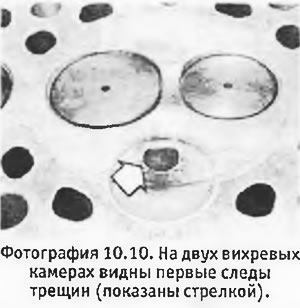
10. Inspect the valve seats and swirl chambers for burns and cracks (see photo). Both seats and inner tubes can be replaced, but this work should be done by a specialist.
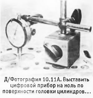
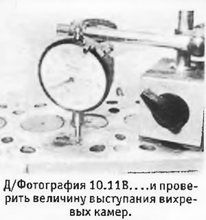
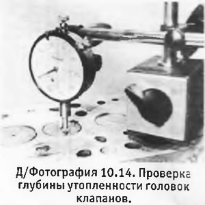
11. Using a dial gauge, check that the protrusion of the swirl chambers does not exceed the specified limits (see Specifications and photographs).
 |
 |
12. Check each valve for warping, burning, cracks, and proper fit in the guide bushing. Excessive valve play in the bushing can be caused by wear of either the valve itself or the bushing. To determine this, you should measure the valve stem with a micrometer or try installing a new valve into the sleeve.
13. The valve guides can be replaced, but this work requires the use of a special press and expander and should be performed by a specialist.
14. Minor defects on the sealing surface of the valve heads can be removed during grinding. More serious defects require regrinding of the valves or their replacement. After grinding the valves, use a dial gauge to check that the valve heads are recessed relative to the cylinder head surface no more than required Specifications.
15. New or reground valves and seats must be lapped together as follows: (if the valves fit well on the seats, you can do without coarse lapping paste).
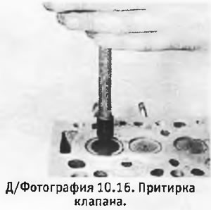
16. Turn the cylinder head over and support it securely. Apply a small amount of coarse carborundum paste to the valve head sealing "belt", insert the valve into its guide bushing and grind it onto the seat using semi-rotary movements. This is usually done using a special valve lapping tool (see photo). The valve should be lifted from time to time to redistribute the paste.
17. Once dull matte stripes appear on the valve seat and head, wipe off the paste and repeat the entire process with fine carborundum paste.
18. After all the valves have been ground into their seats, clean off all traces of lapping paste, first with a rag soaked in kerosene, and then with clean, dry rags. If possible, blow out the valves, seats and guide bushings with compressed air.
19. Inspect the valve springs for fatigue wear and, if possible, compare their length with the length of new springs. If the engine has been running a lot, it is recommended to replace the springs regardless of their condition.
20. Inspect the tappets and their channels for wear and other damage.
21. Inspect the camshaft bearings in the cylinder head and covers. Inspect the camshaft.
22. Inspect the manifold studs and camshaft bearing caps. If necessary, replace them using a special stud puller or with 2 nuts screwed onto the exposed part of the stud thread. If you accidentally remove a stud that is in good condition, you should reinstall it after cleaning its threads and lubricating them with a thread locking compound.
23. Begin assembly by lubricating the stem of the first valve with oil. Lay the cylinder head on its side, insert the valve into the guide bushing and install the spring seat, then the large and small valve springs (by any side) and the spring plate.
24. Compress the springs using a valve spring compressor and install the spring springs. Apply a little grease to the crackers to help them stick to the valve stem and carefully release the springs. Remove the valve spring compressor.
25. Repeat the above procedure on the remaining 7 valves. Replace the valve timing hole plug (if it was filmed).
26. Install the intake and exhaust manifolds with new gaskets and gradually tighten their nuts.
27. Install the glow plugs and tighten them to the specified torque (see chapter 3). Connect the wires to the spark plugs.
28. Install the injectors together with their washers and tighten them to the required torque (see chapter 3). Connect the fuel bypass pipes.
29. Lubricate the tappets with oil and insert them into the channels together with the adjusting washers. Check that all tappets and washers are in their original positions and that the washers are facing down with the size marked on them. Record the thickness of all washers according to their position for subsequent valve clearance adjustments.
30. Install the camshaft.
XUD7T/L Engine - Modifications
1. From the end of 1992, the XUD7T engine fitted to the 205 and 309 models was modified to comply with new European emission control regulations. The modified engine is designated XUD7T/L, where "L" indicates the emission control level. Models equipped with a modified engine have the following designation on the identification plate:
- 205 models 1CV2P
- 309 models without air conditioning 1CV2M
- 309 models with air conditioning 1CV2N
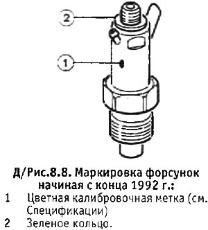
2. The modified engine is equipped with a high-pressure fuel pump and Lucas injectors. The injector holders have two colored identification marks—one on the side of the holder indicating the injector calibration, and the other (green ring on top of the injector), indicating that the injector provides emission control level "L".
Valve stem seals - all engines with the letter "L" in their designation
3. All engines with the letter "L" in their designation (including XUD7T/L), have oil scraper caps for the inlet and outlet valves. These caps must be replaced, regardless of their condition, after each valve removal. Apart from this, the reassembly procedure remains the same as for earlier models.