
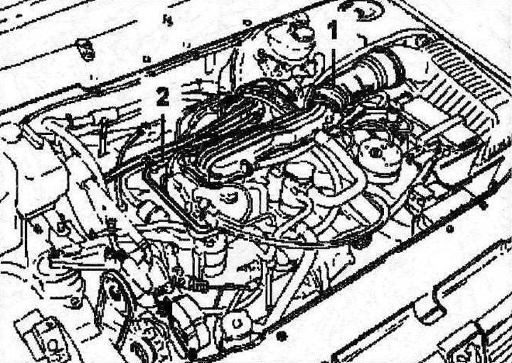
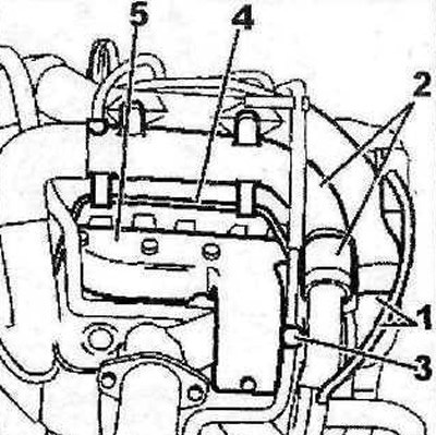
4.1 Disconnect the intake air duct 1, then disconnect and move away from the place of work the fuel lines 2. Vehicles with XU102C engines
2. Vehicles with XU10J2 engines. Remove the air filter, mass air flow sensor, air ducts 3 (see illustration).
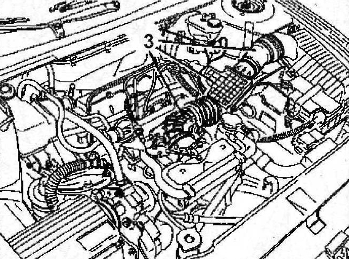
4.2 Remove the air filter, mass air flow sensor, air ducts 3. Vehicles with XU10J2 engines
3. Remove the timing belt, (see relevant chapter).
4. Move the pump away from the place of work, and then the power steering reservoir.
5. Disconnect the intake pipe by unscrewing the bolts 5 and removing their bushings 4 and springs (see illustration).
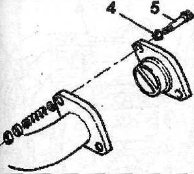
4.5 Disconnect the intake pipe, for which unscrew the bolt 5, remove the bushings 4
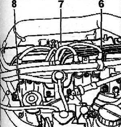
6. Remove cover 6 of the ignition distributor and disconnect the wiring harness from it together with the holder (see illustration).

4.6 Remove cover 6 of the ignition distributor and disconnect the wiring harness from it together with the holder
7. Remove the slider and its protective cover.
8. Disconnect the camshaft position sensor plug.
9. Disconnect the coolant hoses 8, 9 and 10 from the thermostat housing (see illustration 4.6).
10. Disconnect block 11, then - coolant temperature sensor 12 (see illustration).
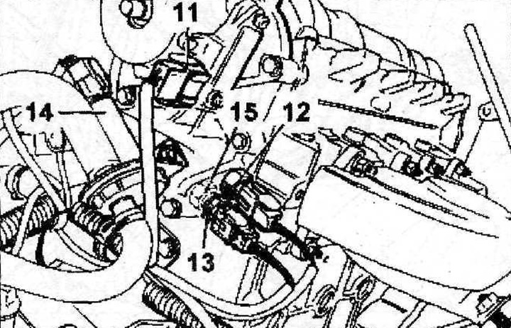
4.11 Disconnect the unit 11, then the coolant temperature sensor 12
12. Vehicles with XU10J2 engines. Disconnect thermistor 13 as well as block 14 (see illustration 4.11)
13. Cars with air conditioning. Disconnect the sensor 15 air conditioner (see illustration 4 11).
14. Vehicles with XU102C engines. Unscrew the bolt 16, then remove the air duct 17 (see illustration),
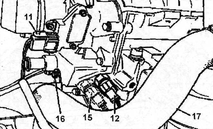
4.14. Unscrew the bolt 15, then remove the air duct 17. Vehicles with XU102C engines
15. Unscrew nuts of fastening of a jellied mouth.
16. Vehicles with XU10J2 engines. Remove the support bracket 18 of the intake manifold and move the manifold away from the place of work (see illustration).
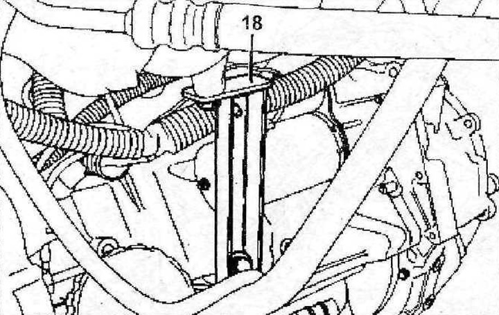
4.16 Remove the intake manifold support bracket 18. Vehicles with XU10J2 engines
17. Vehicles with XU10J2 engines. Remove the support cover with vibration damper 19 (see illustration).
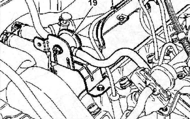
4.17 Remove the support cover with vibration damper 19. Vehicles with XU10J2 engines
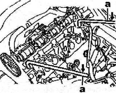
18. Remove the cover 20 of the cylinder head, and then the holder 21 of the guide tube of the measuring probe (see illustration).
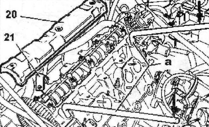
4.18 Remove the cover 20 of the cylinder head, and then the holder 21 of the dipstick guide tube
19. Loosen the tightening, and then unscrew the cylinder head bolts in a diagonal sequence, starting with the outer bolt.
20. Loosen the fit of the cylinder head using special levers «A» (see arrows in illustration 4.18).
21. Remove the cylinder head, remove the cylinder head gasket..
Vehicles with turbocharged XU10J2TE engine
22. Drain the coolant.
23. Disconnect all wiring harnesses and hoses connected to the cylinder head and preventing its dismantling.
24. Disconnect hoses 1 and 2, pipelines 3 and 4, then remove heat deflector 5 (see illustration).
4.24 Disconnect hoses 1 and 2, pipelines 3 and 4, then remove the heat shield 5
25. Unscrew four nuts of fastening of a turbocharger to a final collector. Plug the intake and exhaust ports of the turbocharger with suitable plugs.
26. Disconnect all wiring harnesses, hoses and lines connected to or attached to the intake manifold.
27. Remove the timing belt (see relevant chapter).
28. Remove the right upper engine mount.
29. Disconnect high voltage wires 6 (see illustration).
4.29 Disconnect high voltage wires 6
30. Remove the cover 7 of the cylinder head, then the intake manifold 8 (see illustration 4.29).
31. Working in a spiral, starting with the outer bolt, first loosen and then unscrew the cylinder head bolts.
32. Loosen the fit of the cylinder head using special levers «A» (see arrows in illustration).
4.32 Loosen the cylinder head with the special levers «A» (see arrows)
33. Remove the cylinder head along with the gasket.
Vehicles with XU1OJ4R engine
34. Disconnect air duct 1 (see illustration).
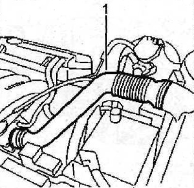
4.34 Disconnect air duct 1
35. Disconnect all wiring harnesses and hoses connected to or attached to the cylinder head and preventing it from being removed.
36. Relieve the pressure in the fuel rail 2. In workshops, a special vacuum pump is used for this «A» (see illustration).
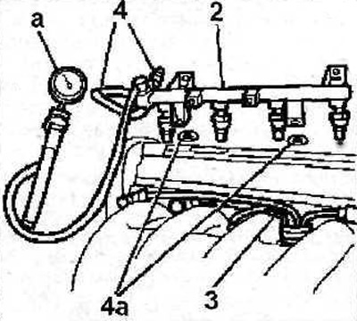
4.36 Relieve the pressure in the fuel rail 2. In workshops, a special vacuum pump is used for this «A»
37. Disconnect the harness 3 fuel injector power wires (see illustration 4.36).
38. Move fuel rail 2 away from the place of work without disconnecting fuel lines 4 from it (See illustration 4.36).
39. Disconnect the hose from the thermostat housing, fastened with a so-called quick clamp (see illustration).
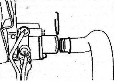
4.39 Disconnect from the thermostat housing the hose fastened with the so-called quick clamp
40. Unscrew the two bolts 5 fastening the intake manifold bracket (see illustration).
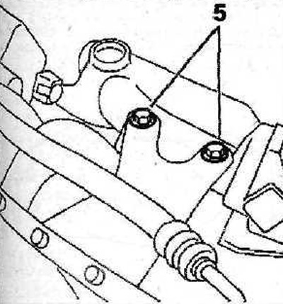
4.40 Unscrew the two bolts 5 fastening the intake manifold bracket
41. Disconnect the front pipe from the exhaust manifold.
42. Remove block 6 ignition coils (see illustration).
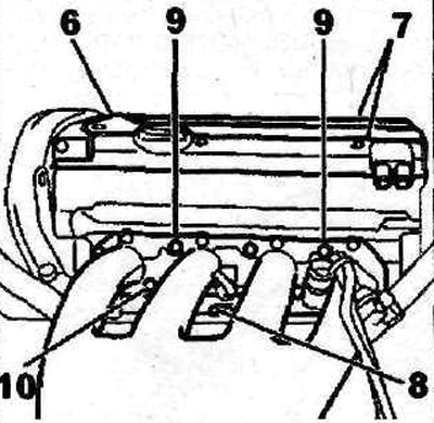
4.42 Remove block 6 ignition coils
43. Working in a spiral, starting with the outer bolt, first loosen and then unscrew the bolts securing both cylinder head covers.
44. Remove covers 7 of the cylinder head (see illustration 4.42).
45. Unscrew the bolt 8, unscrew the nuts 9, unscrew the bolts 10 and remove the intake manifold together with the throttle valve (see illustration 4.42).
46. Remove the timing belt (see relevant chapter).
47. Install the right engine mount.
48. Working in a spiral, starting with the outer bolt, first loosen the tightening, and then unscrew the cylinder head bolts.
49. Loosen the fit of the cylinder head with special levers «A» (see illustration) and remove the head along with the gasket.
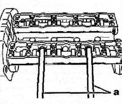
4.49 Loosen the fit of the cylinder head using special levers «A»