
Attention! Do not use sharp-edged tools to clean the cylinder head to prevent damage to the aluminum parts of the cylinder block and the surface of the cylinder head gasket.
51. Clean the holes A of the cylinder head bolts (see illustration).
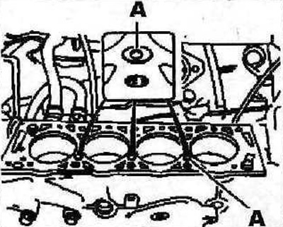
4.51 Clean the holes A of the cylinder head bolts
52. Examine interfaced surfaces of a head and the block of cylinders. They should not have potholes, deep scratches and other damage. Minor defects can be eliminated by machining. In case of significant defects, the parts must be replaced.
53. Clear a carving of bolts of fastening of a head of the block of cylinders. Bolt holes must be free of oil or other contaminants. If necessary, blow out the holes with compressed air or clean with a screwdriver wrapped in rags that will absorb liquid. Oil can be collected from the holes with a grease gun. If this is not done, excessive pressure will be created in the holes when the bolts are screwed in, which can lead to a rupture of the cylinder block or to the wrong tightening torque of the bolts.
54. Check the cylinder head for deformation and warpage using a reference steel ruler, setting the ruler along the lines of measurement (see illustration). Warping within 0.05 mm is allowed.
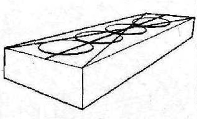
4.54 Check the cylinder head for deformation and warping with a standard steel ruler, setting the ruler along the lines of measurement
55. Measure the length of the cylinder head bolts. The length of their rods X, measured from the bottom surface of the bolt head, must not exceed 122 mm, or 124.5 mm for cars with an XU102TE engine, or 11 2 mm for cars with an XU10J4R engine (see illustration). Otherwise, the bolts should be replaced with new ones.
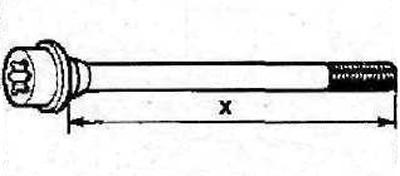
4.55 Measure the length X of the cylinder head bolts
56. Check for dowel pins 1 (see illustration).
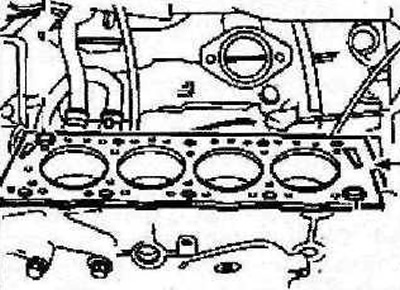
4.56 Check the presence of dowel pins 1
57. Install a new cylinder head gasket. Protrusion B of the gasket must be on the clutch side (see illustration 4.56).
58. Lock the camshaft by installing a suitable thrust roller or stop «A» into the appropriate hole (see illustrations 4.58 and 4.58a). Install the cylinder head in its seat.
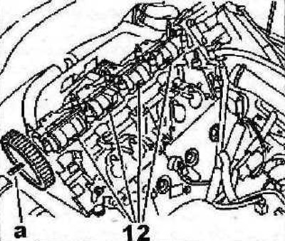
4.58 Lock the camshaft gear a by installing a suitable thrust roller or stop «A» 0153-YES in the appropriate hole. Vehicles with XU10J2TE engine
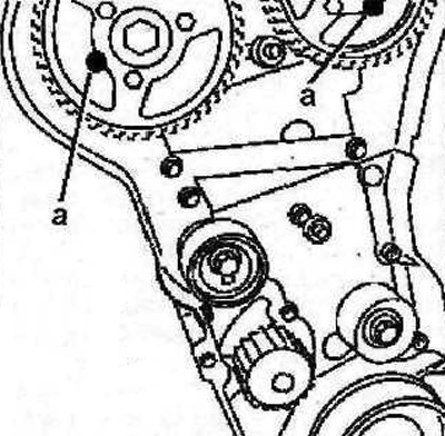
4.58a Lock the camshaft gears by installing suitable thrust rollers or stops «A» 0153-AB into the appropriate holes. Vehicles with XU10J4R engine
59. Lubricate the threads of the cylinder head bolts with MOLYKOTE G RAPID PLUS sealant (see arrows in illustration 4.59) and tighten the bolts, in the sequence shown in illustration 4.59a, in several passes:
- 1st pass - tighten the bolts with a force of 35 Nm;
- 2nd pass - tighten the bolts to 70 Nm;
- 3rd pass - Tighten the bolts 160°.
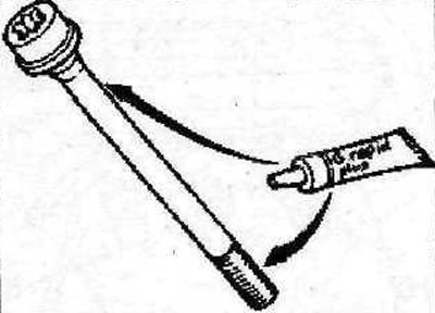
4.59 Lubricate the threads of the cylinder head bolts with MOLYKOTE G RAPID PLUS sealant (see arrows)
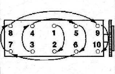
4.59a The sequence of tightening the cylinder head bolts
Further, the installation of the dismantled components is carried out in the reverse order of removal, taking into account the following:
60. Vehicles with XU10J2TE engine. Apply I SILICONE CATEGORIE 2 to areas A (see illustration).
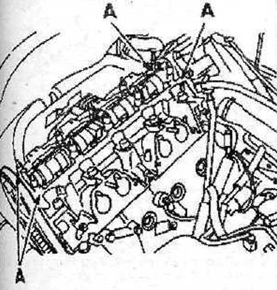
4.60 Apply SILICONE CATEGORIE 2 to areas A. Vehicles with XU10J2TE engine
61. The intake manifold gasket must be replaced.
62. Vehicles with XU10J4R engine. Tightening torque for nuts 2 fastening the right engine mount is 45 Nm, bolts 3 - 60 Nm (see illustration).
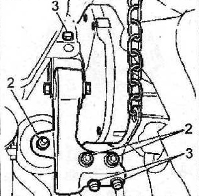
4.62 Tightening torque for nuts 2 fastening the right engine mount is 45 Nm, bolts 3 - 60 Nm. Vehicles with XU10J4R engine
63. Vehicles with XU1OJ4R engine. Install the intake manifold and tighten bolts 4 and nuts 5 of its fastening with a force of 20 Nm, bolt 6 with a force of 10 Nm (see illustration).
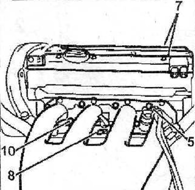
4.63 Install the intake manifold and tighten the bolts 4 and nuts 5 of its fastening with a force of 20 Nm, bolt 6 - with a force of 10 Nm. Vehicles with XU10J4R engine
64. Vehicles with XU1OJ4R engine. Install 7 cylinder head covers (see illustration 4.63).
Attention! Composite cylinder head cover gaskets; Minor gasket damage can be repaired by applying SILICONE CATEGORIE 2 sealant.
65. Vehicles with XU10J4R engine. Tighten the cylinder head cover bolts to 10 Nm in the sequence shown in the illustration.
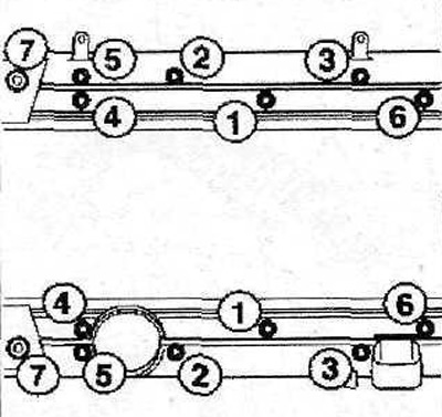
4.65 Tighten the cylinder head cover bolts to 10 Nm in the sequence shown. Vehicles with XU10J4R engine
66. Vehicles with XU10J2TE engine. The tightening torque of nuts 8 and bolts 9 for fastening the right engine mount is 45 Nm, bolt 10 - 55 Nm, bolt 11 - 60 Nm (see illustration).
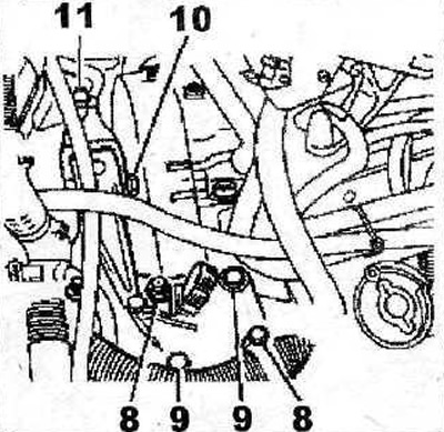
4.66 The tightening torque of nuts 8 and bolts 9 for fastening the right engine mount is 45 Nm, bolt 10 - 55 Nm, bolt 11 - 60 Nm. Vehicles with XU10J2TE engine
67. Upon completion of work, remove air from the cooling system.