
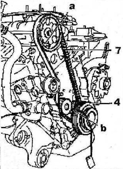
2.33 Install the belt pulley 4 on the crankshaft and fix it with the bolt without performing the final tightening
34. Lock the camshaft gear by inserting a suitable thrust roller or, for example, a stop «A» 0132-R in the corresponding hole (see illustration 2.33).
35. Lock the crankshaft pulley 4 by inserting a suitable thrust roller or, for example, a stop «b» 0153-G in the corresponding hole (see illustration 2.33).
36. Carefully place the toothed belt 7 of the timing drive first on the drive gear, and then on the camshaft gear, water pump pulley and tension roller (see illustration 2.33).
37. Turn the tension roller 8 counterclockwise to tension the toothed belt 7 (see illustration).
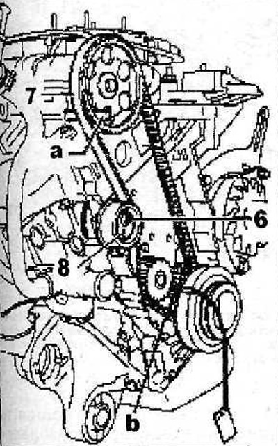
2.37 Turn the tension roller 8 counterclockwise to tension the toothed belt 7
38. Tighten the bolt 6 fastening the tension roller (see illustration 2.37).
39. Remove the stops «A» And «b», which were used to block the camshaft and crankshaft (see illustration 2.37).
40. Gently rotate the crankshaft two turns in the direction of engine rotation.
Attention. Turning the engine in the direction opposite to its direction is not allowed.
41. Check the correct installation of the gas distribution mechanism by installing thrust rollers to block the crankshaft and camshaft in the appropriate holes. If the mechanism is installed correctly, then the rollers will freely enter both holes and fix the crankshaft and camshaft. Otherwise, repeat the procedure for laying the toothed belt.
42. Remove the thrust roller that was used to block the crankshaft.
43. Fix the sensor «A» device for measuring the tension of the toothed belt in the section 7 of the belt between the camshaft and crankshaft (see illustration).
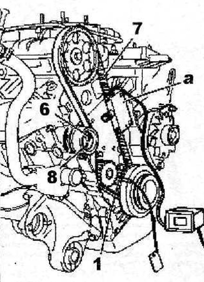
2.43 Fix the sensor «A» a device for measuring the tension of the toothed belt in section 7 of the belt between the camshaft and crankshaft
44. Loosen the bolt 6 fastening the tension roller 8 and move it away from the toothed belt, thereby loosening its tension (see illustration 2.43).
45. Turn the tension roller 8 (see illustration 2.43) counterclockwise until the belt tension is 18 SEEM. Tighten the tensioning roller mounting bolt with a force of 20 Nm, remove the measuring device.
46. Gently rotate the crankshaft two turns in the direction of engine rotation.
47. Check the correct installation of the gas distribution mechanism by installing thrust rollers to block the crankshaft and camshaft in the appropriate holes. If the mechanism is installed correctly, then the rollers will freely enter both holes and fix the crankshaft and camshaft.
48. Reattach the sensor «A» a device for measuring the tension of the toothed belt in section 7 of the belt between the camshaft and crankshaft (see illustration 2.43).
49. Read the readings of the measuring device. Belt tension should be 42-46 SEEM. Otherwise, repeat the toothed belt tension adjustment procedure.
50. Remove the belt tension measuring device, and also remove the thrust rollers
51. Install all other dismantled components in the reverse order of removal.
52. Lubricate the threads of the bolts 9 fastening the upper part of the protective cover of the gas distribution mechanism with LOCTITE sealant, screw in the bolts and tighten them with a force of 10 Nm (see illustration).
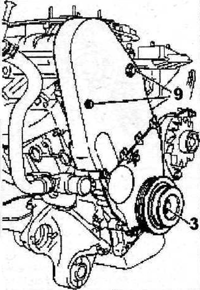
2.52 Lubricate the threads of bolts 9 fastening the upper part of the protective cover of the gas distribution mechanism drive with sealant
53. Tighten the bolt 3 fastening the belt pulley on the crankshaft (see illustration 2.52) with a force of 110 Nm, having previously lubricated the bolt threads with THREADLOCK LOCTITE sealant.
Vehicles with XU10J4R engine
54. Check the ease of movement of rollers 13 and 14 (see illustration). Lay the toothed belt on the crankshaft gear, following the marks made during removal.
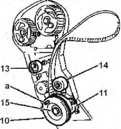
2.54 Check the ease of movement of rollers 13 and 14
55. Install the protective cover 11, then the pulley 10, tightening the bolt 15 of its fastening with a force of 120 Nm (see illustration 2.54). Before screwing in, the bolt 15 of the belt pulley on the crankshaft must be lubricated with LOCTITE FRENETANCH sealant.
56. Lock the crankshaft by installing a suitable thrust roller or, for example, a stop «A» 0153-G in the corresponding hole (see illustration 2.54).
57. Loosen the bolts 16 for fastening the camshaft gears, check the ease of movement of the gears 17 and 18 on the hubs 19 (see illustration).
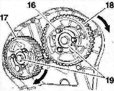
2.57 Loosen the bolts 16 of the fasteners of the camshaft gears, check the ease of movement of the gears 17 and 18 on the hubs 19
58. Tighten by hand six bolts 16 fastening the gears of the camshafts (see illustration 2.57), then back off 1/6 turn.
59. Turn gears 17 and 18 in the direction of engine rotation so that the gear mounting bolts are in the center of the elongated holes, and do not rest against their ends (see arrows in illustration 2.57).
60. Lay the toothed belt on the gear on the crankshaft, and then on the tension roller.
61. Lay the toothed belt 20 on the gear wheel 18 of the camshaft. If necessary, turn the camshaft gear against the direction of engine rotation to align the belt teeth with the gear slots (see arrow in illustration).
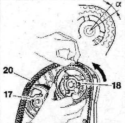
2.61 Lay the toothed belt 20 on the gear wheel 18 of the camshaft. If necessary, turn the camshaft gear against the direction of engine rotation to align the belt teeth with the gear slots (see arrow)
Attention! Bias «A» belt tooth in the corresponding gear recess should not exceed the width of one tooth (see illustration 2.61).
62. Similarly, lay the toothed belt on the gear 17 of the camshaft (see illustration 2.61).
63. Lay the timing belt on the tension roller and water pump gear.
64. Make sure the camshaft gears are locked - stops «A» are in the corresponding holes (see illustration).
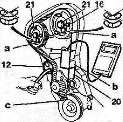
2.64 Make sure the camshaft gears are locked - stops «A» are in the corresponding holes
65. Attach the sensor «b» device for measuring tension on section 20 of the toothed belt (see illustration 2.64).
66. Turn the tension roller 12 counterclockwise so that the belt tension is 45 SEEM units (see illustration 2.64).
67. Tighten the tension roller mounting bolt with a force of 20 Nm without changing the position of the roller.
68. Make sure that the bolts 16 for fastening the camshaft gears are in the center of the elongated holes, and do not abut against their ends (see illustration 2.64). For this purpose, one of the bolts can be unscrewed. If the bolts are not centered, the toothed belt installation procedure must be repeated. Tighten the camshaft gear bolts to 10 Nm. Remove the device for measuring the tension of the toothed timing belt drive, as well as the thrust rollers «A» And «With», which were used to block the camshafts and crankshafts.
69. Gently turn the crankshaft two turns in the direction of engine rotation.
Attention! Turning the engine in the direction opposite to its direction is not allowed.
70. Lock the crankshaft again by installing a suitable thrust roller or, for example, a stop «With» 0153-G in the corresponding hole (see illustration. 2.64).
71. Loosen the bolts 16 fastening the gears of the camshafts (see illustration 2.64), then hand-tighten the bolts and loosen 1/6 turn again.
72. Lock the camshaft gears by setting the stops «A» into the corresponding holes. If necessary, turn the gears a little by the bolts 21 for fastening the shaft hubs so that the stops enter the holes without hindrance (see illustration 2.64).
73. Reinstall the toothed belt tension gauge, loosen the idler pulley mounting bolt and read the gauge readings: the belt tension should be 26 SEEM units.
74. Tighten the tension roller mounting bolt with a force of 20 Nm and the camshaft gear mounting bolts with a force of 10 Nm. Remove any tools that were used to measure belt tension and lock the crankshaft and camshaft.
75. Perform a final toothed belt tension check by making sure the crankshaft is locked.
76. Loosen the camshaft gear bolts, then tighten the bolts by hand and again loosen the tightening by 1/6 turn.
77. Lock the camshaft gears by inserting stops into the appropriate holes. If necessary, turn the gears a little by the bolts of the shaft hubs so that the stops fit into the holes without hindrance.
78. Tighten the camshaft gear bolts to 10 Nm.
79. Remove the stops that were used to block the crankshaft and camshafts.
80. Gently rotate the crankshaft a quarter of a turn in the direction of engine rotation.
81. Reinstall the toothed belt tension gauge and read the gauge: the belt tension should be 32-40 SEEM. Otherwise, repeat the toothed belt tension adjustment procedure.
82. Remove the belt tension measuring device, and also remove the thrust rollers
83. Further, the installation of the dismantled components is carried out in the reverse order of removal.
84. Tighten the nuts 22 for fastening the support 5 of the engine mount with a force of 45 Nm, and bolts 23-60 Nm (see illustration).
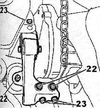
2.84 Tighten the nuts 22 for fastening the support 5 of the engine mount with a force of 45 Nm, and the bolts 23-60 Nm