



Table of contents: Removal 🠇 Installation 🠇
Removal
The cylinder head can be removed without removing the engine from the vehicle. However, it should be taken into account that the timing belt will have to be partially removed. It is also important to remember that the new head gasket must be the same thickness as the old one. If the removal of the cylinder head is necessary to replace valves, pre-chambers or other parts, we recommend entrusting the work to a workshop. The work on disassembling and overhauling the valve timing mechanism specified for gasoline engines is generally also applicable to this type of diesel engine.
All engines
1. Disconnect the negative (-) battery terminal.
2. Place the front of the vehicle on jack stands and remove the engine splash guard.
3. Remove the V-belt to provide better access to the engine. This is especially true for 2.1 liter engines.
4. Remove the air filter together with the hoses (see illustration).
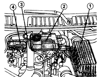
20.4 Remove the air filter and the following parts
1 - air filter
2 - coolant expansion tank
3 - air intake sleeve
4 - cylinder head cover
Next to the hose there is an eye 3 for lifting the engine (1.9-liter engine), which must be disconnected (see illustration 20.5).
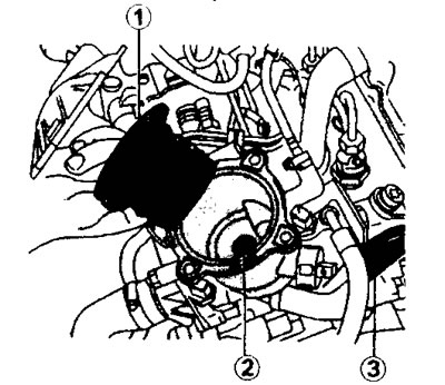
20.5 Remove the replaceable filter element 1 of the fuel filter and unscrew the bolt that secures the lower part of the filter
5. Remove the replaceable fuel filter element and unscrew the bolt that secures the lower part of the filter (see illustration)
6. Remove the cylinder head cover.
7. Unscrew the mounting bolts and disconnect the exhaust pipe together with the gasket.
8. Disconnect all wires, hoses and pipes from the cylinder head.
9. Drain the coolant.
10. Disconnect the exhaust pipe from the turbocharger.
11. Release the EGR power supply wire, unscrew the nuts that secure the turbocharger and remove it.
12. Disconnect the intake manifold and remove it by pushing it upwards (see illustration)
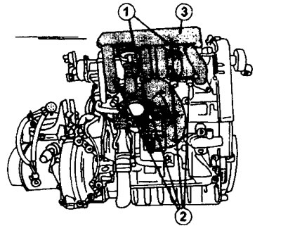
20.12 Release the EGR supply wire, unscrew the nuts securing the turbocharger and remove it, and also disconnect and remove the intake manifold. The illustration shows a 1.9 liter engine
13. Release the engine mounts from the cushions to transfer the weight of the engine to the front mount. After this, disconnect the right engine mount bracket.
14. Remove both timing belt guards.
15. Fix the crankshaft from turning with a rod if you are disassembling a 1.9 liter engine, installing it as shown in illustrations 17.77. Before this, the crankshaft must be turned to set the engine to TDC.
16. Prepare three M8x1.5 mm bolts, 40 mm long. Insert one bolt into hole 4 on the camshaft gear, and the remaining two into holes 6 and 7 on the fuel injection pump gear (see illustration).
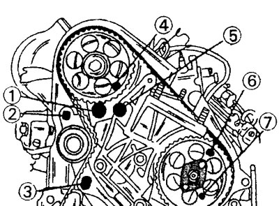
20.16 Front side of the engine after removing the timing belt guards.
1 - hole for a square on the toothed belt tensioner
2 - timing belt tensioner bolt
3 - timing belt tensioner bolt
4 - thrust bolt in the camshaft gear hole
5 - engine support bracket bolt
6 - thrust bolt in the hole of the fuel injection pump gear
7 - thrust bolt in the hole of the fuel injection pump gear
Original publication on the website [peugeotbook]
These bolts install fairly easily if the crankshaft is installed properly. Installing bolts allows you to secure the timing mechanism.
17. Unscrew both bolts 2 and 3 securing the toothed belt tensioner and, inserting a 3/8 inch square wrench into hole 1 of the tensioner, press the tension roller outward to loosen the toothed belt tension. Tighten bolt 2 again to secure the tensioner in its new position (see illustration 20.16).
18. Remove the toothed belt from the gears by feeding it forward.
19. Loosen the timing belt gear mounting bolt on the camshaft and remove the gear from the shaft. While doing this, hold the gear from turning.
20. Unscrew the cylinder head mounting bolts in several passes in the reverse order of screwing. The length of the bolts must be measured before they are installed during assembly. Stretched bolts must be replaced with new ones (see illustration).
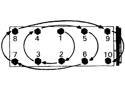
20.20 Sequence of screwing in and tightening the cylinder head mounting bolts. When removing the head, the bolts are unscrewed in the reverse order
Due to the fact that the cylinder head is installed on a centering pin, separating the head from the cylinder block is quite difficult. In workshops, pry bars with ends bent at a 90° angle are used to remove the head. Both pry bars, with the bent ends inserted into the mounting bolt holes, are lifted simultaneously. The raised cylinder head is moved slightly to the side to remove the camshaft from the support. Make sure the centering pin remains in the cylinder block. If the pin is removed together with the cylinder head, it must be pulled out of the head and inserted into the cylinder block (see illustration 20.20a).
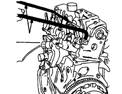
20.20a To remove the cylinder head, use pry bars with ends bent at an angle of 90°.
21. Clean the mating surfaces of the cylinder head and block using a suitable cleaning agent. Surfaces must not be cleaned with a hard scraper or sandpaper. Grinding of the cylinder head is also not permitted. If the camshaft rotates freely, then it does not need to be modified.
After dismantling the cylinder head, remove the corresponding parts and take out the valves (see the relevant chapter).
Installation
22. Clean the holes for the cylinder head mounting bolts. The holes must be free of oil and the threads must be in good condition. If necessary, the thread can be renewed with an appropriate tap (thread M12x150). The contact surfaces of the cylinder head and cylinder block must be thoroughly cleaned.
23. Set the camshaft to TDC. This means that the valves of cylinders #1 and #4 should be in the closed position.
24. Place in the left corner (when viewed from the front) cylinder block centering pin. In the opposite corner of the block, screw in the centering pin. This pin is unscrewed with a screwdriver after installing the cylinder head.
25. Select a sealing gasket of the same thickness as the previous one. Place the gasket on the cylinder block so that the tab with the gasket marking faces the correct direction. When purchasing a new sealing gasket, it is recommended to present the old one.
26. Measure the length of the cylinder head mounting bolts. The head of the cylinder head bolts for the XUD9 engine is designed for a socket wrench. Other engines may use bolts with a head that fits a special key. The length of the bolts is measured on the segment X (see illustration).
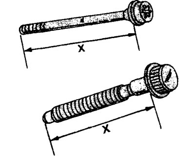
20.26 The bolt length measurement is taken along the X-segment. The upper bolt without a shoulder is used on 1.9-liter engines, and the lower one is used on 2.1-liter engines
When measuring bolts, please note that bolts without a shoulder at the bottom end may be used (engines XUD9 and XUD11) or with a shoulder (XUD11). If the length of the bolts without a shoulder is greater than 146.8 mm (see illustration 20.26), then such bolts must be replaced with new ones.
The same applies to shoulder bolts if their length is over 151.5 mm (see illustration 20.26).
27. Install the cylinder head. Place the head at a slight angle so that the centering pin fits into the corresponding hole in the cylinder head. After this, release the head completely so that it is installed on the cylinder block. The auxiliary centering pin must now be unscrewed with a screwdriver.
28. Lubricate the bolt threads and washers with oil and screw the bolts into the holes. A socket wrench is used to tighten the cylinder head bolts (xUD9 engines) or a special key (xUD11 engines). In addition, you will need a protractor to tighten the bolts.
29. Tighten the bolts in the sequence shown in (illustrations 20.29).
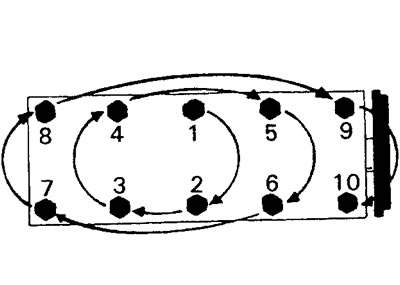
20.29 Tighten the cylinder head bolts in the sequence shown
The procedure is as follows.
30. Tighten all bolts in the sequence shown to a torque of 20 Nm, then tighten them to a torque of 60 Nm.
31. Tighten all bolts an additional 180°, or half a turn. This can be accomplished with a ratchet.
Subsequent tightening of the cylinder head bolts is not necessary.
32. Install the timing belt sprocket onto the camshaft. Secure the gear to the shaft with a bolt with a tightening torque of 45 Nm, while holding the gear from turning.
33. Adjust the valve clearance (see the relevant chapter). Valve clearance is adjustable only on 1.9 liter engines.
34. Install the timing belt.
All other parts are installed in place in the reverse order of removal.